Archives 2024

Kinematics: Understanding Uniform Motion

Kinematics: Understanding Uniform Motion

Kinematics: Understanding Uniform Motion

What is Kinematics 

Kinematics is the branch of physics that deals with the motion of objects without considering the causes of motion. Among the various types of motion, uniform motion is a fundamental concept that provides a foundation for understanding more complex movements. In this article, we will delve into the intricacies of uniform motion, explore its characteristics, and see its applications in our daily lives.

What is Uniform Motion?

Uniform motion refers to the movement of an object at a constant speed in a straight line along specific fixed direction. In other words, the object covers equal distances in equal intervals of time, regardless of how small these intervals might be. This type of motion is characterized by:

  • Constant Velocity: The speed/magnitude of velocity and direction of the object’s motion remain unchanged.
  • Zero Acceleration: Since the velocity is constant, there is no change in speed or direction, resulting in zero acceleration.

As , \overrightarrow{v\;}\;=\;constan t\;

Therefore, \overrightarrow{a\;}=\;\frac{d\overrightarrow v}{dt}=\;0

Mathematical Representation

Consider an object is moving along +X axis with uniform velocity ‘v’ as shown in diagram. Assume that object is at position x=x_1 at time t=t_1 and reaches at position x=x_2 at time t=t_2
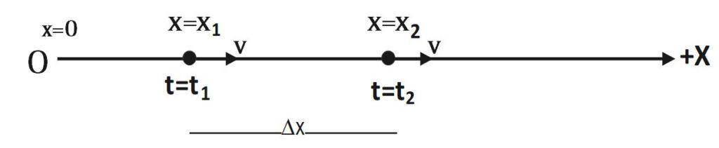
Kinematics: Understanding Uniform Motion

We know that velocity of object is defined as rate change of position of object w.r.t. time. Mathematically,

v=\frac{dx}{dt}\;

\Rightarrow dx\;=\;v\;dt\;

\int_{x_1}^{x_2}dx\;=\;\int_{t_1}^{t_2}v\;dt\;

\int_{x_1}^{x_2}dx\;=\;v\int_{t_1}^{t_2}\;dt\; (v= constant/uniform)

\left|x\right|_{x_1}^{x_2}=\;v\;\left|\;t\;\right|_{t_1}^{t_2}

x_2\;-x_1\;=\;v\;(t_2-t_1)

\Delta x\;=v\;\Delta t

v=\frac{\Delta x}{\Delta t}

Hence,\;v=\frac{dx}{dt}=\frac{\Delta x}{\Delta t}=constant

Clearly, uniform motion reflects that the object covers equal distances in equal intervals of time, regardless of how small these intervals might be.

When object/particle starts motion from origin (x=0)

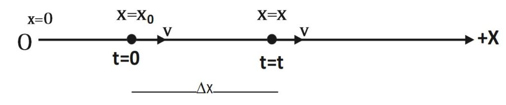
When particle starts motion from origin then initial displacement of particle is zero i.e. at t= 0 , x=0 . And it moves with constant velocity v, finally reaches at P in time t. Thus, at time t = t , x = x as shown in following diagram .

We know that for uniform motion, 

\Delta x\;=v\;\Delta t

x-0= v(t-0)

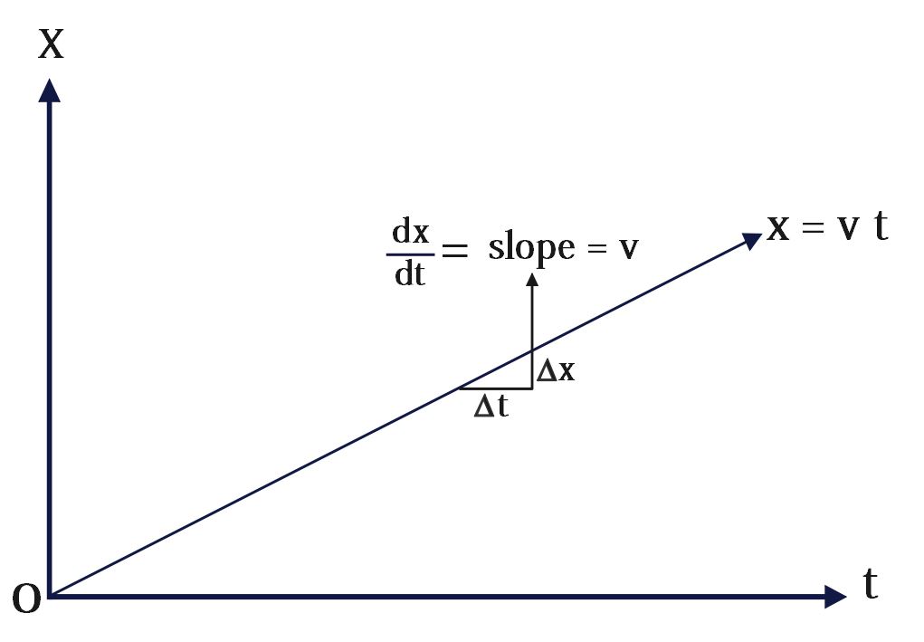
x = v t
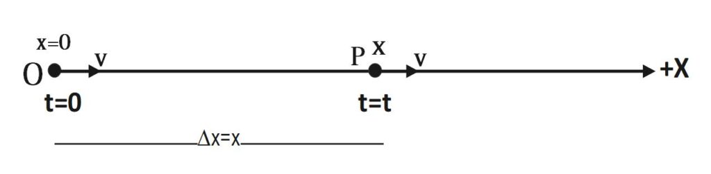
Kinematics: Understanding Uniform Motion

Position-Time (x-t) graph of uniform motion starting from origin
Kinematics: Understanding Uniform Motion

When object/particle starts motion with some initial displacement

When particle does not starts motion from origin but from x= x_o then initial displacement of particle is non-zero i.e. at t=0 , x= x_o  .  With constant velocity v, it finally reaches at position x in time t as shown in following diagram . Thus, at time t = t , x = x 

We know that for uniform motion, 

\Delta x\;=v\;\Delta t

x-x_o= v(t-0)

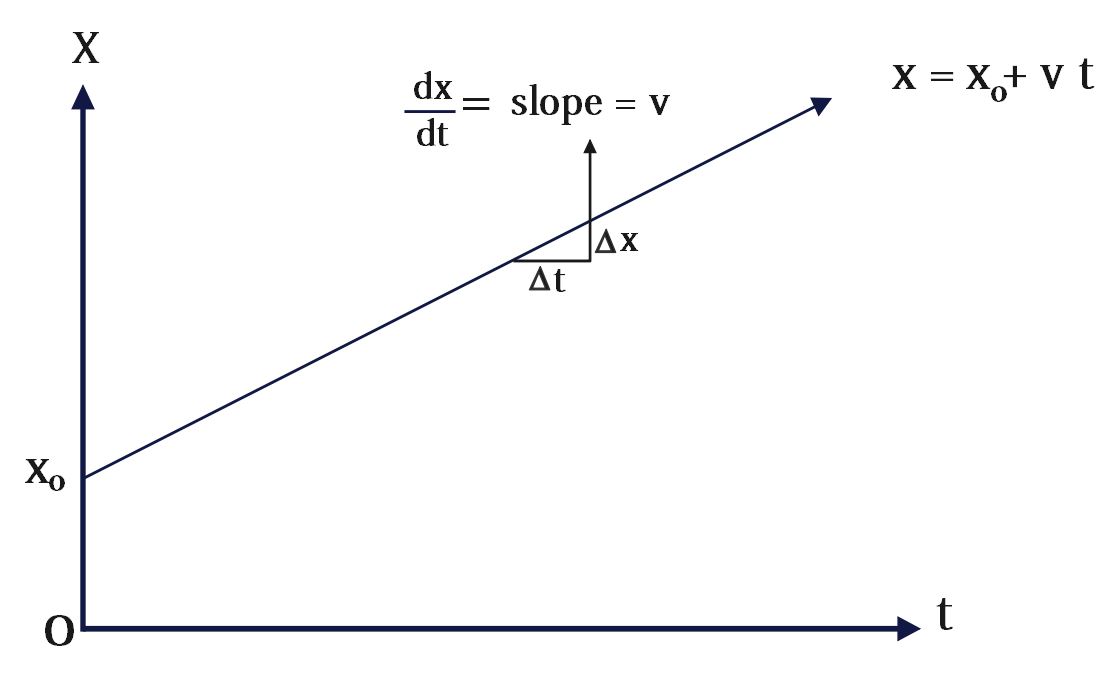
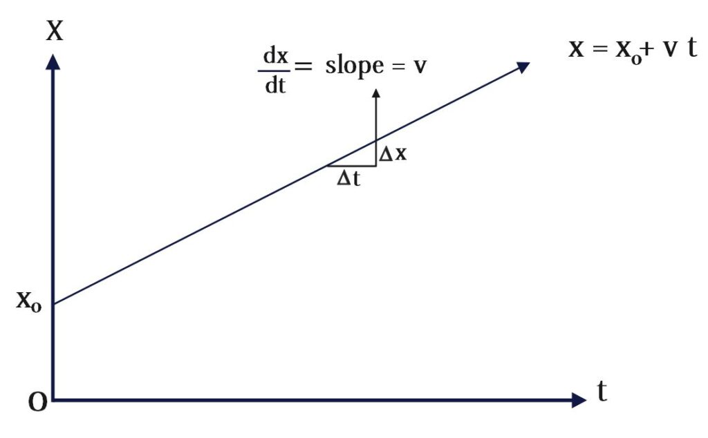
x = x_o+ v t
Kinematics: Understanding Uniform Motion

Position-Time(x-t) graph of uniform motion of particle with non-zero initial displacement
Kinematics: Understanding Uniform Motion

Graphical Representation

Position-Time Graph

In a distance-time graph for uniform motion, the distance (y-axis) plotted against time (x-axis) yields a straight line with a constant slope. The slope of this line equals the velocity of the object.

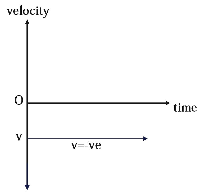
Velocity-Time Graph

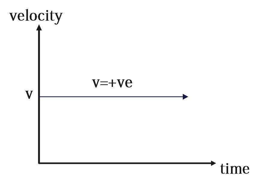
In a velocity-time graph for uniform motion, the velocity (y-axis) plotted against time (x-axis) is a straight horizontal line. This horizontal line indicates that the velocity remains constant over time.
Kinematics: Understanding Uniform Motion

Uniform Motion vs. Non-Uniform Motion

Understanding the difference between uniform and non-uniform motion is crucial. While uniform motion features a constant velocity, non-uniform motion involves a change in speed or direction, indicating acceleration. Real-world motions are often non-uniform due to varying forces acting on objects, but uniform motion serves as an idealized model to simplify analysis.

Conclusion

Uniform motion, with its simplicity and predictability, is a cornerstone concept in kinematics. It lays the groundwork for more complex analyses of motion in physics and engineering. By grasping the fundamentals of uniform motion, one can better understand the intricate dynamics of moving objects, both in theoretical contexts and real-world applications. Whether it’s a car cruising on a highway or the precise movement of a spacecraft, uniform motion continues to be a vital principle in the study of mechanics.
Force between the plates of charged capacitor

Force between the plates of capacitor

Force between the plates of capacitor

Introduction

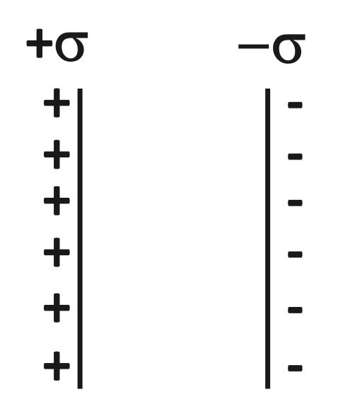
Capacitors are fundamental components in electronics, used to store electrical energy. When a voltage is applied across the plates, an electric field develops, causing a charge to accumulate on the plates. The capacitor stores energy in the electric field created between the plates.

Among various types of capacitors, the parallel plate capacitor is one of the simplest and most widely studied. Understanding the force between the plates of a charged parallel plate capacitor not only deepens our comprehension of electrostatic principles but also has practical applications in various technologies.

Derivation of Force between the Plates of Capacitor

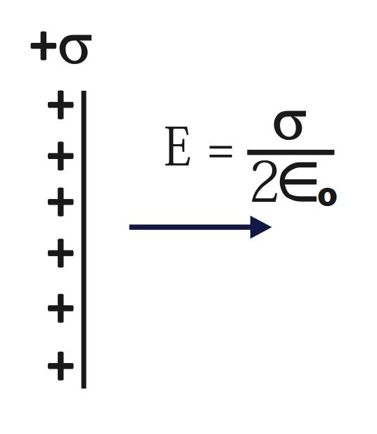
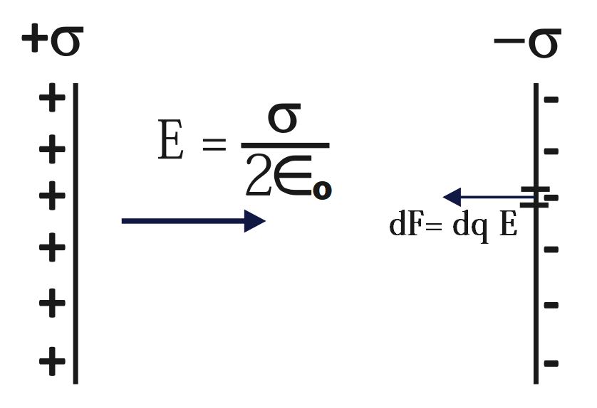
To derive the force between the plates, let us consider the small element of charge dq on second plate. Thus, calculate the force of attraction due to the electric field (of first plate) on small element of charge on second plate (-vely charged). 

We already know that,
E=\;\frac\sigma{2\in_o} 
Force between the plates of capacitor
Force due to uniform electric field E on small element dq
dF\;=\;dq\;E  
Integrating both sides
\int dF\;=\;\int dq\;E  
F\;=\;E\;\int dq\; (As, E = constant)
F\;=\;E\;q
F\;=\;\left(\frac\sigma{2\in_o}\right)\;q
F\;=\;\left(\frac q{2A\in_o}\right)\;q
F\;=\frac{q^2}{2A\in_o}
Hence, we have obtained that the formula of force between the plates of capacitor
F\;=\frac{q^2}{2A\in_o}

Practical Implications

Understanding of the force between the plates of a capacitor is crucial for several reasons:

  1. Mechanical Stability: In high-voltage applications, the force can be significant, potentially leading to mechanical deformation or even damage if the capacitor is not designed to handle such forces.

  2. Design Considerations: Engineers need to consider this force when designing capacitors to ensure they remain stable and functional under varying electrical conditions.

  3. Microelectromechanical Systems (MEMS): In MEMS devices, capacitors can be used as actuators where the force between plates is used to move microstructures.

Transient Current : Charging of Capacitor

Transient Current: Charging of Capacitor with DC source

Charging of Capacitor with DC source - IIT Advanced Topic

Transient Current :

Transient current is a temporary current that flows for a short, finite duration, starting from zero to a maximum value or from a maximum value to zero, in response to a sudden change in the circuit conditions, such as when a switch is turned on or off.

Charging of Capacitor : Introduction

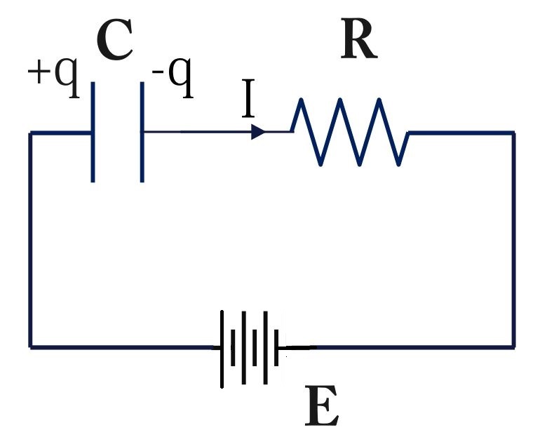
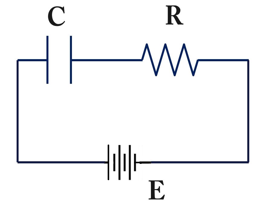
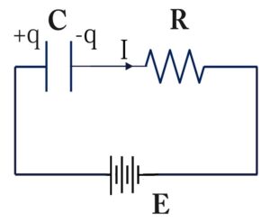
Capacitor with DC source is practically CR circuit. In the capacitor charging there are three stages:

  1. Initial Condition:

    • When an uncharged capacitor is connected to a voltage source through a resistor, the transient current initially flows from zero to a maximum value.
  2. Exponential Decay:

    • The current then decreases exponentially over time as the capacitor charges, described by the equation:
      I(t)\;=\;I_o\;e^{-\frac t{CR}}
      where E is the applied voltage, is the resistance, is the capacitance, and 𝑡 is the time elapsed.
  3. Steady State:

    • Once the capacitor is fully charged, the current drops to zero, indicating the end of the transient period. 
      I\;=\;\frac{dq_0}{dt}=\;o\;
Initial Condition
Transient Current: Charging of Capacitor with DC source
When switch is just closed, time, t=0 and capicitor is uncharged . So, Charge q=0
Also, intially the current will be maximum.
hence, I_o=\;\frac ER
Steady State
Transient Current: Charging of Capacitor with DC source
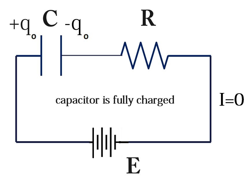
Capacitor continues getting charged until it is fully charged . This is called steady state.

As, we know that 

I\;=\;\frac{dq_0}{dt}=\;o\; 

where q_o is maximum charge

Therefore, according to Kirchhoff’s loop rule

E\;-\;\frac{q_o}C-(0)\;R=\;0


E\;-\;\frac{q_o}C=\;0


E\;=\;\frac{q_o}C


q_o\;=\;EC…….(1)


Assume that capacitor is charged up to charge q at any time t.
Therefore, time = t and charge = q
According to Kirchhoff's loop rule,
E-\;\frac qC-IR\;=\;0
EC-q-ICR\;=\;0
EC-q-\frac{dq}{dt}\;(CR)\;=\;0
q_o-q-\frac{dq}{dt}\;(CR)\;=\;0 [from(1)]
\frac{q_0-q}{CR}-\;\frac{dq}{dt}=0
\frac{q_0-q}{CR}=\;\frac{dq}{dt}
\frac1{CR}\;dt\;=\;\frac{dq}{q_o-q}\;
Integrating both sides
\int_0^t\frac1{CR}\;dt\;=\;\int_0^q\frac{dq}{q_o-q}\;
\frac1{CR}\int_0^t\;dt\;=\;\int_0^q\frac{dq}{q_o-q}\;
\frac1{CR}\;\left|t\right|_0^t\;\;=\;\;\left|\frac{\log_e\left(q_o-q\right)}{-1}\right|_0^q
\frac1{CR}(t-0)\;\;=\;\;-\;\lbrack\log_e\left(q_o-q\right)-\;\log_e\left(q_o-0\right)\rbrack
-\frac t{CR}\;=\;\;\;\log_e\left(\frac{q_o-q}{q_o}\right)
e^{-\frac t{CR}\;}\;=\;\frac{q_o-q}{q_o}
q_o\;e^{-\frac t{CR}\;}\;=\;q_o-q
\;q=q_o-\;q_o\;e^{-\frac t{CR}\;}\;
\;q=q_o(1-\;\;e^{-\frac t{CR}\;}\;)
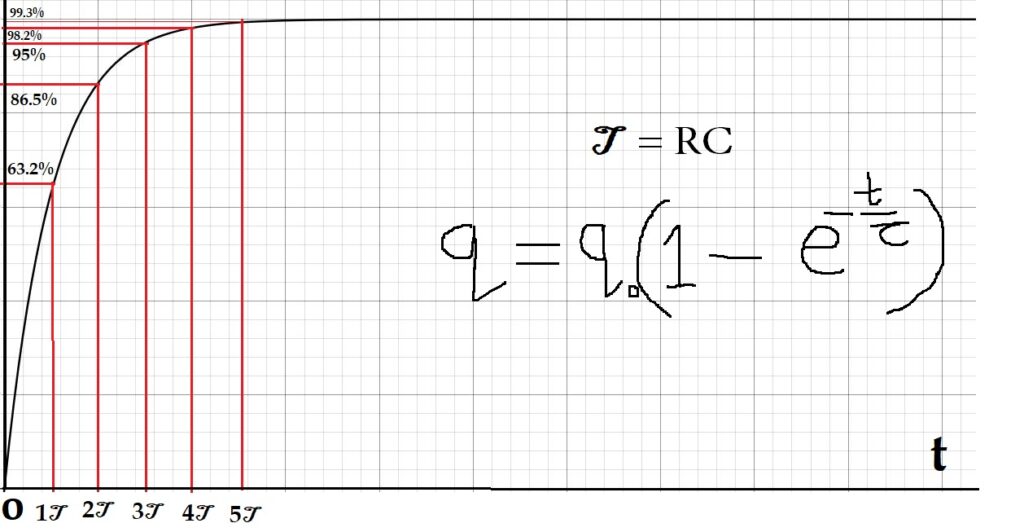
q=\;q_o\;(1-e^{-\frac t\tau})
\tau = CR is called Time Constant

When time t=\;1\;\tau

So, q=\;q_o(1-\;e^{-1})\;=\;0.632\;q_o

Capacitor gets charged by 63.2% in first time constant

When time t=\;2\;\tau

So, q=\;q_o(1-\;e^{-2})\;=\;0.865\;q_o

Capacitor gets charged by 86.5% in two time constants

When time t=\;3\;\tau

So, q=\;q_o(1-\;e^{-3})\;=\;0.950\;q_o

Capacitor gets charged by 95% in three time constants

When time t=\;4\;\tau

So, q=\;q_o(1-\;e^{-4})\;=\;0.982\;q_o

Capacitor gets charged by 98.2% in four time constants

When time t=\;5\;\tau

So, q=\;q_o(1-\;e^{-5})\;=\;0.993\;q_o

Capacitor gets charged by 99.3% in five time constants

When steady state is attained, capacitor is fully charged

t\;\rightarrow\infty

q=\;q_o(1-\;e^{-\infty})\;

q=\;q_o(1-\;0)=\;q_o

So, q=\;q_o

\;q=q_o(1-\;\;e^{-\frac t{CR}\;}\;)
taking derivative both sides w.r.t. t
\frac{dq}{dt}=q_o\;\frac d{dt}(1-\;e^{-\frac t{CR}})
\frac{dq}{dt}=q_o\;\lbrack\;0-\;e^{-\frac t{CR}}\;\times\;(-\frac1{CR}\;)\;\rbrack
\frac{dq}{dt}=\;\frac{q_o}{RC}\;\;e^{-\frac t{CR}}\;
\frac{dq}{dt}=\;\frac{EC}{RC}\;\times\;e^{-\frac t{CR}}\;
\frac{dq}{dt}=\;\;\frac ER\;\times\;e^{-\frac t{CR}}\;
I=\;\;I_o\;\times\;e^{-\frac t{CR}}\; [ From (1) ]
I=\;\;I_o\;\;e^{-\frac t{CR}}\;

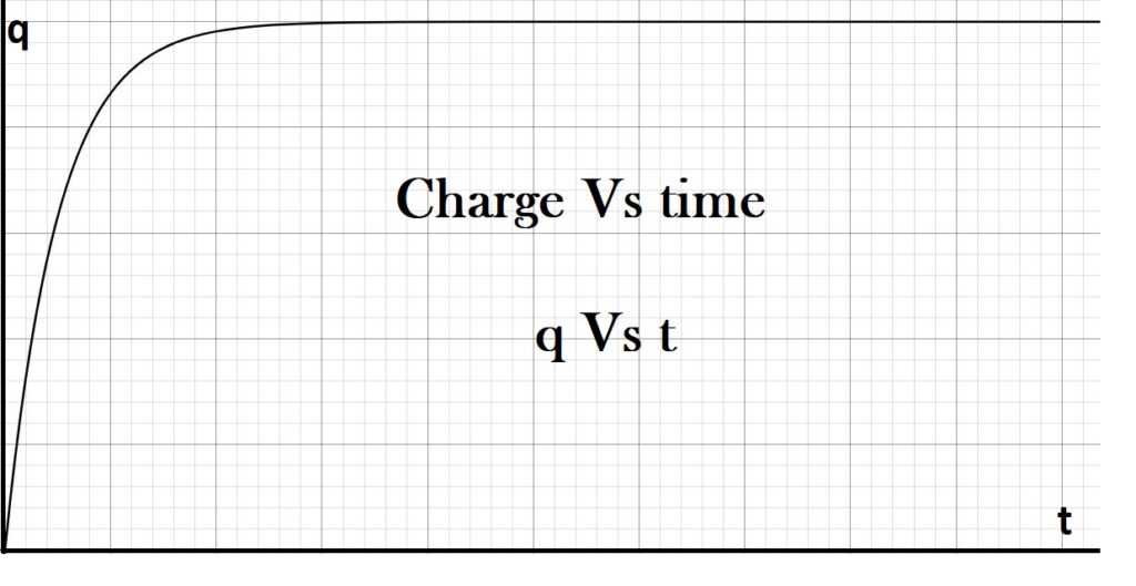
Exponential Growth of Charge : Charging of Capacitor

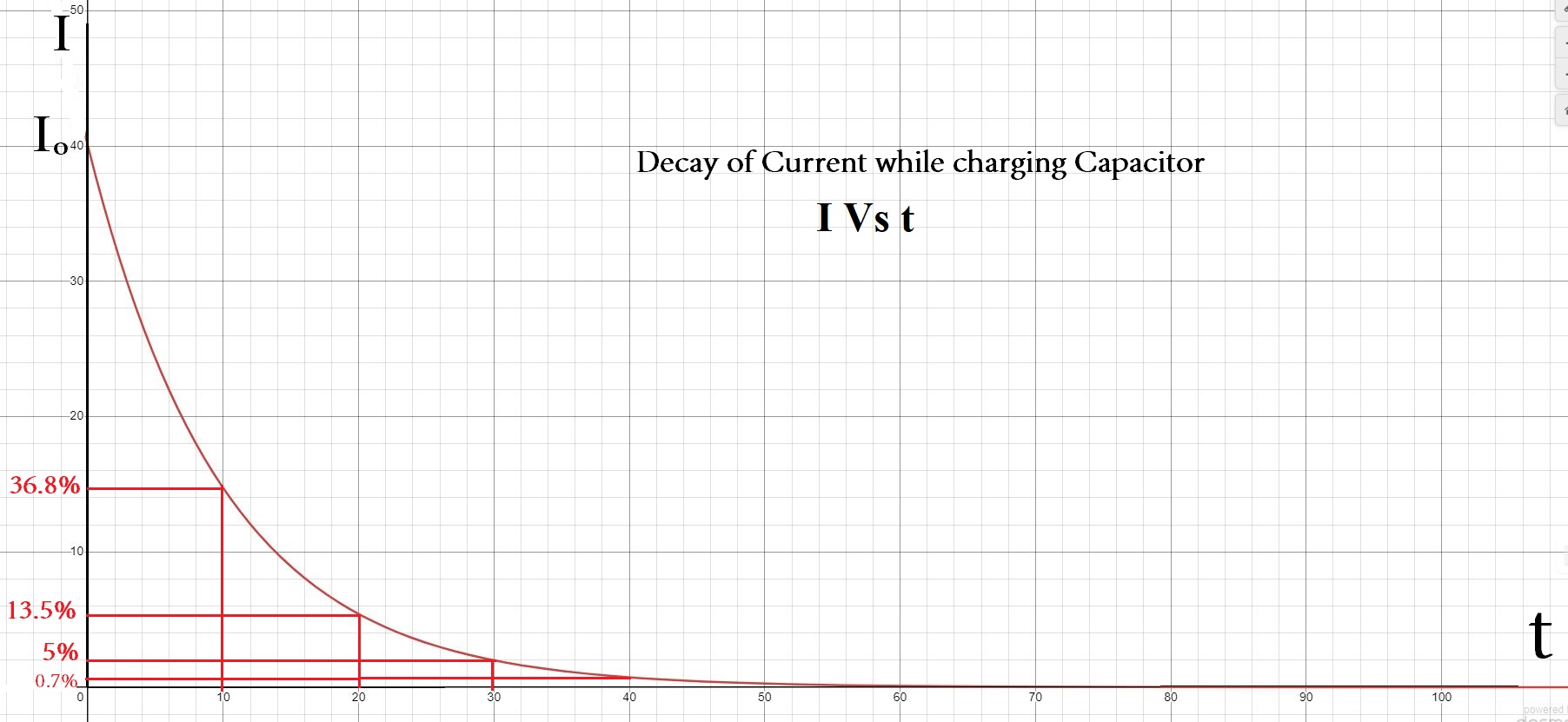
Exponential Decay of Current : Charging of Capacitor

I=\;\;I_o\;\;e^{-\frac t{CR}}\;

I=\;I_o\;e^{-\frac t\tau}

I=\;I_o\;e^{-\frac t\tau}

When time t=\;1\;\tau

I=\;\;I_o\;e^{-1}\;

I=\;0.368\;I_o\;

So, current reduces by 62.8% of maximum current in 1 time constant

When time t=\;2\;\tau

I=\;\;I_o\;e^{-2}\;

I=\;0.135\;I_o\;

So, current reduces by 86.5% of maximum current in 2 time constants

When time t=\;3\;\tau

I=\;\;I_o\;e^{-3}\;

I=\;0.05\;I_o\;

So, current reduces by 95% of maximum current in 3 time constants

When time t=\;4\;\tau

I=\;\;I_o\;e^{-4}\;

I=\;0.018\;I_o\;

So, current reduces by 98.2% of maximum current in 3 time constants

When time t=\;5\;\tau

I=\;\;I_o\;e^{-5}\;

I=\;0.07\;I_o\;

So, current reduces by 99.3% of maximum current in 3 time constants

When steady state is achieved , then current reduces to zero

t\;\rightarrow\infty

I=\;\;I_o\;e^{-\infty}\; =0

Charging of Capacitor : An Overview

Initially, when switched is just on ,  capacitor is is uncharged and it offers zero resistance to DC source and current is maximum(largest possible). Thus, we can calculate the value of maximum current by formula,  I_o=\;\frac ER 

Finally, steady state is attained after some time (theoretically , when  t\;\rightarrow\infty ) and capacitor gets fully charged. Now, capacitor starts blocking DC (direct current) and it reduces to zero i.e. I = 0

Consequently, maximum charge is q_o\;=\;EC

During charging of capacitor , current falls from I_o to 0 . This is known as decay of current. It is found that the decay of current is exponential decay as according to formula  I=\;\;I_o\;\;e^{-\frac t{CR}}\;      

Numerical based on Charging of Capacitor

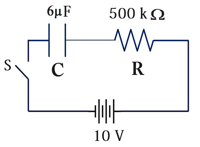
Ex. An uncharged capacitor and a resistor are connected in series, as shown in the figure below. The emf of the battery is ε = 10 V, C = 6 μF, and R = 500 kΩ.

After the switch is closed, find

(a) The time constant of the RC circuit.

(b) The maximum charge on the capacitor.

(c) The charge on the capacitor 6 s after the switch is closed.

(d) The charge on the capacitor 8.1 s after the switch is closed.

Solution:

(a) Time Constant, \tau = CR
\tau\;\;=\;6\mu\;\times\;500\;k=\;6\;\times10^{-6}\;\times\;500\;\times10^3
\tau\;\;=\ 3 s
(b) The maximum charge on the capacitor
Charge wll be maximum when steady state is achieved and capacitor gets fully charged, q_o=\;C\;E
q_o=\;6\times10^{-6}\times10\;=\;60\;\mu C
q_o =\;60\;\mu C
(c) The charge on the capacitor 6 s after the switch is closed.
Charge on capacitor at any instant t, q=\;q_o\;(1-e^{-\frac t\tau})
q(t)=\;q_o\;(1-e^{-\frac t\tau})
q(6)=\;q_o\;(1-e^{-\frac 63})
q(6)=\;60\;(1-e^{-2})
q(6)=\;60\;(1-0.135)
q(6)=\;60\;(0.865)
q(6)\;=\;51.9\;\mu C\;\approx\;52\;\mu C\;
q(6)\;=\;52\;\mu C\;
(d) The charge on the capacitor 8.1 s after the switch is closed.
Charge on capacitor at any instant t, q=\;q_o\;(1-e^{-\frac t\tau})
q(t)=\;q_o\;(1-e^{-\frac t\tau})
q(8.1)=\;q_o\;(1-e^{-\frac {8.1}3})
q(8.1)=\;60\;(1-e^{-2.7})
q(8.1)=\;60\;(1-0.067)
q(8.1)=\;60\;(0.933)
q(8.1)\;=\;55.98\;\mu C\;\approx\;56\;\mu C\;
q(8.1)\;=\;56\;\mu C\;

Electrostatics-10 Important basic MCQs (Quiz) Part 3

Electrostatics-10 Important basic MCQs (Quiz) Part 3

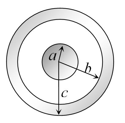
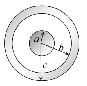
1. A solid conducting sphere of radius a has a net positive charge 2Q. A conducting spherical shell of inner radius and outer radius c is concentric with the solid sphere and has a net charge – Q. The surface charge density on the inner and outer surfaces of the spherical shell will be 

Electrostatics-10 Important basic MCQs (Quiz) Part 3

(A) -\frac{2Q}{4\mathrm{πb}^2},\;\frac Q{4\mathrm\pi\;\mathrm c^2}

(B) -\frac{Q}{4\mathrm{πb}^2},\;\frac Q{4\mathrm\pi\;\mathrm c^2}

 (C) 0, \frac Q{4\mathrm\pi\;\mathrm c^2}

(D) None of the above

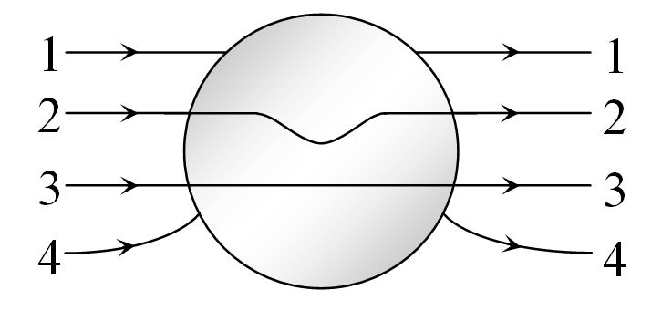
2. A metallic solid sphere is placed in a uniform electric field. The lines of force follow the path(s) shown in figure as:

Electrostatics-10 Important basic MCQs (Quiz) Part 3

(A)   1   

(B)  2

 (C) 3                              

(D) 4

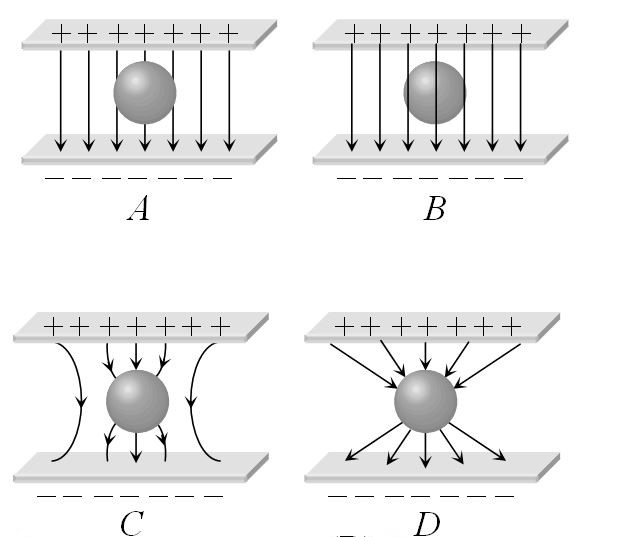
3.An uncharged sphere of metal is placed in between two charged plates as shown. The lines of force look like

Electrostatics-10 Important basic MCQs (Quiz) Part 3

(A) A                     

(B) B

(C) C                      

(D) D

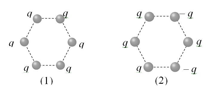
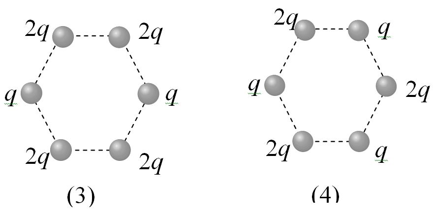
4.Figures below show regular hexagons, with charges at the vertices. In which of the following cases the electric field at the centre is not zero

(A) 1                                       

(B) 2

(C) 3                             

(D) 4

5. Two point charges +8q and -2q  are located at x=0  and  x=L respectively.  The location of a point on the x-axis at which the net electric field due to these two point charges is zero is

(A) 8 L                           

(B) 4 L

(C) 2 L                           

(D) \frac L4


6. At a certain distance from a point charge the electric field is 500 V/m and the potential is 3000V/m . What is this distance

(A)  6m                         

(B) 12m

(C) 36m                       

 (D) 144m

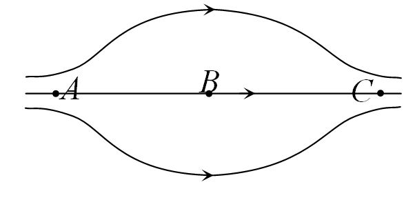
7. The figure shows some of the electric field lines corresponding to an electric field. The figure suggests

(A)E_A>\;E_B>\;E_C                

(B) E_A=\;E_B=\;E_C 

(C) E_A=\;E_C>\;E_B                

(D) E_A=\;E_C<\;E_B   

8. Point charges +4q, -q and +4q are kept on the axis at points x=0, x=a and  x=2a respectively, then

(A) Only  ‘-q’ is in stable equilibrium

(B) None of the charges are in equilibrium

(C) All the charges are in unstable equilibrium

(D) All the charges are in stable equilibrium

9. Two point charges of 20\;\mu C\; and 80\;\mu C\;  are   10 cm  apart. Where will the electric field strength be zero on the line joining the charges from 20\;\mu C\; charge

(A) 0.1 m                         

(B)0.033 m 

(C) 0.33 m                

(D) 0.04 m

10. What is the magnitude of a point charge which produces an electric field of 2 N/coulomb at a distance of 60 cm 

(A) 8\;\times\;10^{-11}\;C

(B) 2\;\times\;10^{-12}\;C

(C) 3\;\times\;10^{-11}\;C

(D) 6\;\times\;10^{-10}\;C


Electrostatics-10 Important basic MCQs (Quiz) Part 1

Electrostatics-10 Important basic MCQs (Quiz) Part 2

Electrostatics-10 Important basic MCQs (Quiz) Part 2

Electrostatics-10 Important basic MCQs (Quiz) Part 2

Electrostatics-10 Important basic MCQs (Quiz) Part 2

1.ABC is a right angled triangle in which AB= 3 cm  and BC = 4cm  . And \angle ABC\;=\frac{\mathrm\pi}2 . The three charges +15, +12    and  -20 e.s.u. are placed respectively on  A, B  and C . The force acting on B is 

(A) 125 dyne

(B) 35 dynes

 (C) 25 dynes

(D) Zero

2.Electric charges of 1\mu C, -1\mu C and 2\mu C  are placed in air at the corners A, B and C respectively of an equilateral triangle ABC having length of each side 10 cm. The resultant force on the charge at C is

(A) 0.9 N                       

(B) 1.8 N

(C) 2.7 N                       

(D) 3.6 N

3. Two charges placed in air repel each other by a force of 10^{-4} N . When oil is introduced between the charges, the force becomes 2.5\;\times\;10^{-5}\;N.The dielectric constant of oil is

(A) 2.5                         

B) 0.25

(C) 2.0                           

(D) 4.0

4. Two spherical conductors B and C having equal radii and carrying equal charges in them repel each other with a force F when kept apart at some distance. A third spherical conductor having same radius as that of B but uncharged is brought in contact with B, then brought in contact with C and finally removed away from both. The new force of repulsion between B and C is

 (A) F/4                         

(B) 3F/4

(C) F/8                

(D) 3F/8

5. The charges on two sphere are +7µC and –5µC They experience a force F. If each of them is given and additional charge of – 2µC, the new force of attraction will be

 (A) F                             

(B) F / 2

(C)  \frac F{\sqrt3}                 

(D) 2F

6. Electric lines of force about negative point charge are

(A) Circular, anticlockwise  

(B) Circular, clockwise

(C) Radial, inward

(D) Radial, outward

7. A charge q is placed at the centre of the line joining two equal charges  Q. The system of the three charges will be equilibrium, if  is equal to

(A) -\frac Q2                          

(B)-\frac Q4    

(C) +\frac Q4                             

(D) +\frac Q2    

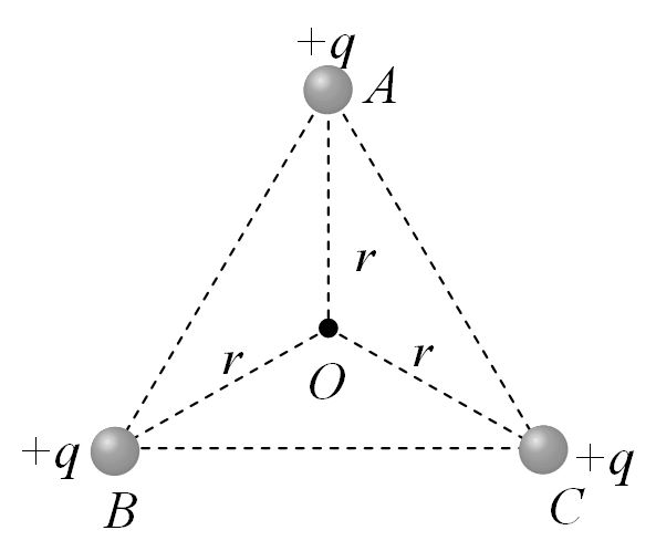
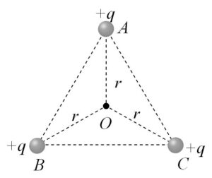
8. ABC is an equilateral triangle. Charges +q are placed at each corner. The electric intensity at O will be

Electrostatics-10 Important basic MCQs (Quiz) Part 2

 (A)\frac1{4\mathrm\pi\;\in_{\mathrm o}}\frac q{r^2}

(B)\frac1{4\mathrm\pi\;\in_{\mathrm o}}\frac{3q}{r^2}

(C) Zero

(D)\frac1{4\mathrm\pi\;\in_{\mathrm o}}\frac qr

9. The electric field inside a spherical shell of uniform surface charge density is

(A) Zero

(B) Constant, less than zero

(C) Directly proportional to the distance from the centre

 (D) None of the above

10.When a body is earth connected, electrons from the earth flow into the body. This means the body is…..

 (A) Unchanged

(B) Charged positively

(C) Charged negatively  

(D) An insulator

Electrostatics-10 Important basic MCQs (Quiz) Part 1

Electrostatics-10 Important basic MCQs (Quiz) Part 1

Electrostatics-10 Important basic MCQs (Quiz) Part 1

1.An isolated solid metallic sphere is given charge +Q.  The charge will be distributed on the sphere       

 (A) Uniformly but only on surface

(B) Only on surface but non-uniformly

(C) Uniformly inside the volume

(D) Non-uniformly inside the volume

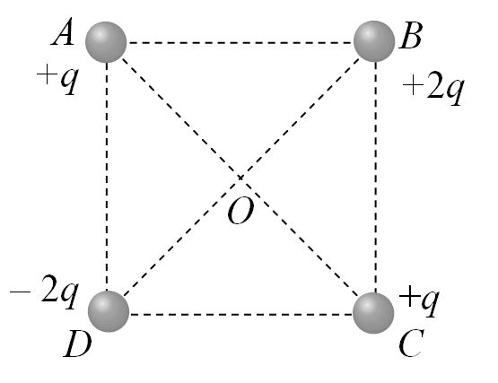
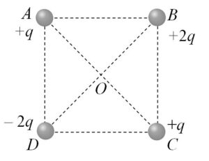
2. Four charges are arranged at the corners of a square ABCD, as shown in the adjoining figure. The force on the charge kept at the centre O is

Electrostatics-10 Important basic MCQs (Quiz) Part 1

(A) Zero

(B) Along the diagonal AC

(C) Along the diagonal BD

(D) Perpendicular to side AB

3.The ratio of the forces between two small spheres with constant charge in (a) air  (b) in a medium of dielectric constant K is
(A) 1 : K                        

(B) K : 1

(C) 1: K^2  

(D) K^2 : 1     

4. Three charges 4q , Q and q  are in a straight line in the position of 0, l/2,  and l respectively.   The resultant force on q will be zero, if  Q=

(A) – q                           

(B) – 2q

(C) -\frac q2 

(D)  4q

5.Two charges each of 1 coulomb are at a distance 1 km apart, the force between them is  

(A)     9\;\times\;10^3\;Newton\;         

(B) 9\;\times\;10^{-3}\;Newton\;  

(C) 1.1\;\times\;10^{-4}\;Newton\;

(D) 10^4\;Newton\;  

6. There are two metallic spheres of same radii but one is solid and the other is hollow, then

 (A) Solid sphere can be given more charge

 (B) Hollow sphere can be given more charge

(C) They can be charged equally (maximum)

(D) None of the above

7. Three equal charges are placed on the three corners of a square. If the force between q_1 and q_2 is F_{12}  and that between q_1  and q_3 is F_{13} , the ratio of magnitudes \frac{F_{12}}{F_{13}} is 

(A) \frac12                     

(B) 2 

(C)  \frac1{\sqrt2}\;

(D) \sqrt{2\;} 

8. Two small spheres each having the charge Q are suspended by insulating threads of length  from a hook. This arrangement is taken in space where there is no gravitational effect, then the angle between the two suspensions and the tension in each will be

(A) 180^o,\;\frac1{4\mathrm\pi\;\in_{\mathrm o}}\frac{Q^2}{{(2L)}^2}   

(B)   90^o,\;\frac1{4\mathrm\pi\;\in_{\mathrm o}}\frac{Q^2}{{L}^2}

(C)    180^o,\;\frac1{4\mathrm\pi\;\in_{\mathrm o}}\frac{Q^2}{2 L^2}           

(D)    180^o,\;\frac1{4\mathrm\pi\;\in_{\mathrm o}}\frac{Q^2}{  L^2}           

9. A soap bubble is given a negative charge, then its radius

(A) Decreases

(B) Increases

 (C) Remains unchanged

(D) Nothing can be predicted as information is insufficient

10. With the rise in temperature, the dielectric constant of a liquid

(A) Remains unchanged

(B) Changes erratically

(C) Increases                 

(D) Decreases


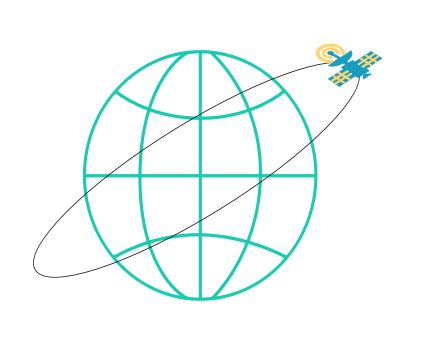
A spaceship is launched into a circular orbit close to the earth’s surface. What additional velocity has now to be imparted to the spaceship in the orbit to overcome the gravitational pull.

Additional velocity

Additional Velocity Required to Overcome Earth's Gravitational Pull for Satellite Escape

Escape velocity is the minimum velocity an object must attain to break free from the gravitational attraction of a massive body without further propulsion. For an object on the surface of the Earth, this velocity is approximately 11.2 kilometers per second (or about 25,000 miles per hour). But for a satellite already in orbit, the calculation is little more complex.

Satellites in low Earth orbit (LEO) typically travel at speeds around 8 kilometers per second (km/s). This velocity, known as orbital velocity, is necessary to counteract the gravitational force pulling the satellite towards Earth, allowing it to maintain a stable orbit.

However, what if we seek to free a satellite from Earth’s gravitational grasp altogether? Escaping Earth’s gravitational influence requires imparting additional velocity to the satellite. Suppose we have a satellite orbiting near the Earth’s surface, with an orbital velocity of approximately 8 km/s. To break free from Earth’s gravity, an additional velocity of approximately 3.2 km/s is needed.

Example

Q.A spaceship is launched into a circular orbit close to the earth's surface. What additional velocity has now to be imparted to the spaceship in the orbit to overcome the gravitational pull. Radius of earth =6400 km , g= 9.8 ms^{-2}

(A) 3.2 km/s

(B) 11.2 km/s

(C) 1.5 km/s

(D) 8 km/s

Solution

We know that , orbital speed of satellite is
v_o=\;\sqrt{\frac{GM}r}\;
where\;r\;is\;dis\tan ce\;from\;centre\;of\;planet/earth
Also, r= R+ h where R is radius of planet/earth and h is height of satellite from surface of earth
v_o=\;\sqrt{\frac{GM}{R+h}}\;
Near to earth's surface, h can be neglected
So, R\;+\;h\;\approx\;R
v_o=\;\sqrt{\frac{GM}{R}}\;
v_o=\;\sqrt{\frac{gR^2}{R}}\;
v_o=\;\sqrt{gR}\;
v_o\;=\;\sqrt{Rg}\approx\;8\;km/s\;
v_e\;=\;\sqrt{2Rg}\approx\;11.2\;km/s\;
Addition velocity required is
v_{add}\;=\;v_e\;\;-\;v_{o\;}
v_{add}\;=11.2 - 8 = 3.2 km/sec
(A) is correct option
Additional velocity

Conclusion

This additional velocity is crucial for overcoming the gravitational potential energy barrier that binds the satellite to Earth. When the satellite reaches this escape velocity, its kinetic energy surpasses the gravitational potential energy, allowing it to break away from orbit and venture into interplanetary space.

Kepler’s law of period

Kepler's law of period

Kepler's law of period for planetary motion

According to Kepler’s laws  of period for planetary motion, the square of the period of revolution of as planet around the sun is directly proportional to the cube of the semi-major axis of its orbit.

Mathematically, it can be expressed as T^2 = k a^3 , where is the orbital period of the planet, is the semi-major axis of its orbit, and is a constant that is the same for all planets orbiting the Sun. 

Example

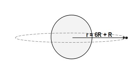
Q.A geostationary satellite is orbiting the earth at a height of 6R above the surface of earth where R is the radius of earth. The time period of another satellite at a distance of 3.5 R from the centre of earth is

(A) 16.96 hours

(B) 8.48 hours

(C) 9.25 hours

(D) 15.76 hours

Solution

We know that , orbital speed of satellite is
v_o=\;\sqrt{\frac{GM}r}\;
where\;r\;is\;dis\tan ce\;from\;centre\;of\;planet/earth
T\;=\frac{dis\tan ce\;}{speed}=\;\frac{2\pi\;r}{v_o}
T\;=\;\frac{2\pi\;r}{\sqrt{\displaystyle\frac{GM}r}}
T\;=\;2\pi\;\sqrt{\frac{r^3}{GM}}
T\;=\;2\pi\;\sqrt{\frac{r^3}{GM}}\\T^2=\;4\;\pi^2\;\frac{r^3}{GM}
\Rightarrow T^2\;\;\propto\;r^3
This is known as Kepler's Law of period for planetary motion
r= R+ h where R is radius of planet/earth and h is height of satellite from surface of earth
\Rightarrow r_1 = R+ 6R=7R \;and \;r_2= 3.5R
\Rightarrow T\;\propto\;r^\frac32
\frac{T_2}{T_1}=\;\left(\frac{r_2}{r_1}\right)^\frac32
\frac{T_2}{T_1}=\;\left(\frac{3.5R}{7R}\right)^\frac32
\frac{T_2}{T_1}=\;\left(\frac{1}{2}\right)^\frac32
\frac{T_2}{T_1}=\frac1{2\sqrt2}
T_2 =T_1 * \frac1{2\sqrt2}
T_2 =24 * \frac1{2\sqrt2}
T_2 =12* \frac1{\sqrt2}
T_2 =12* 0.707= 8.48 \;hours
(B) is correct option

Conclusion

Kepler’s third law is also known as law of period which helps us to find the time period of orbital motion for various distances from sun. It includes following  applications. 

  1. Predicting Planetary Motion: Kepler’s law of periods allows astronomers to predict the orbital periods of planets based on their distances from the sun. This law has been crucial in the study of our solar system and in the discovery and characterization of exoplanets in other solar systems.

  2. Comparing Orbits: By comparing the orbital periods and semi-major axes of different planets or moons, astronomers can gain insights into the structure and dynamics of planetary systems. For example, comparing the orbital periods of moons around a planet can provide information about their relative distances from the planet.

  3. Verification of Kepler’s Laws: Kepler’s laws of planetary motion played a significant role in the development of Newton’s law of universal gravitation and the laws of motion. They served as a crucial test for Newtonian physics and provided evidence for the gravitational force between celestial bodies.

Moment of Inertia of a Rod having non-uniform, linearly increasing mass density

Moment of Inertia of Rod having non-uniform, linearly increasing mass density

Moment of Inertia of Rod having non-uniform, linearly increasing mass density

Moment of Inertia

Moment of inertia is of great importance when we come to discuss the rotational dynamics. The the word “inertia” refers to resistance against any change in state of object (mass). Specifically, the moment of inertia is measure of a body’s resistance to changes in its rotation. The greater the value of moment of inertia, the more is difficulty it is to cause change in its rotation.

The moment of inertia is often denoted as “I” and it is analogous to mass (m) of the object. In linear motion, mass quantifies an object’s resistance to linear acceleration (change in velocity) in response to a force. Similarly, in rotational motion, the moment of inertia quantifies an object’s resistance to angular acceleration (change in angular velocity) in response to a torque. Moreover, both are scalar quantities.  

Factors affecting Moment of Inertia

Here are the main factors affecting the moment of inertia:

  • Mass Distribution

  • Shape of the Object

  • Axis of Rotation

  • Size and Dimensions

  • Symmetry

Infact, we can can generalize the above all factor into one key factor – the mass distribution of body about axis of rotation which incorporates he definition of moment of inertia. 

I= m_1 r_1^{2} + m_2 r_2^{2}+ …… m_n r_n^{2} . Lets consider following example to grasp the concept of moment of inertia.

Example - On Moment of Inertia of Rod

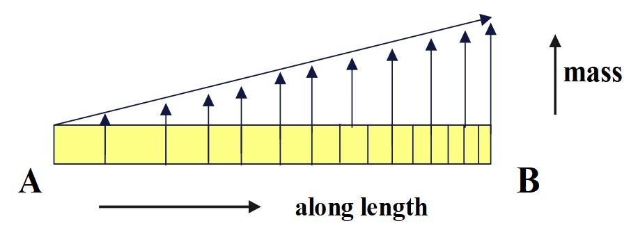
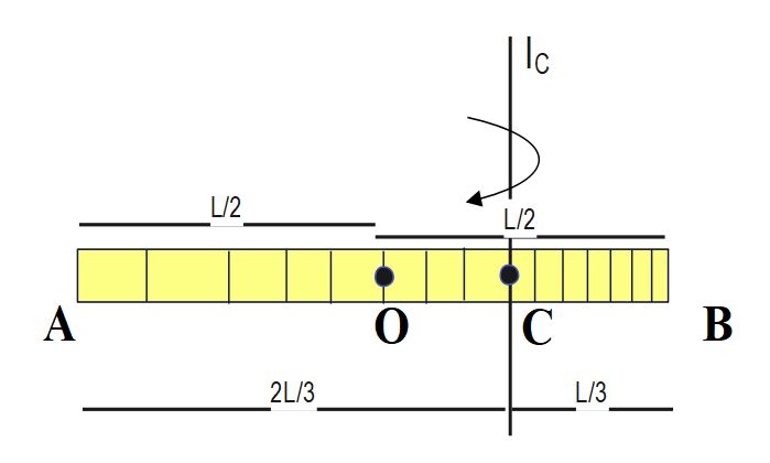
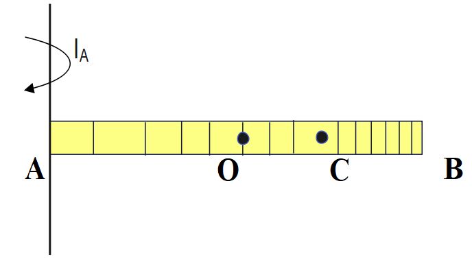
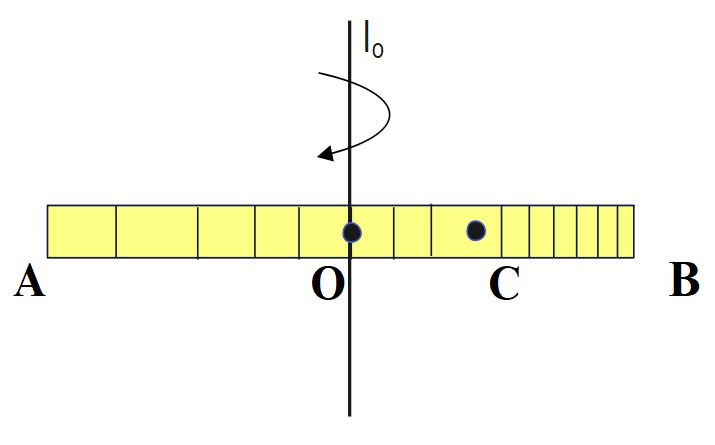
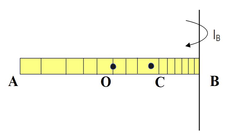
The density of a rod AB increases linearly from A to B. Its mid-point is O and centre of mass is at C. Four axes pass through A, B, O and C , all perpendicular to the length of rod. The moments of inertia of the rod about these axes are I_{A}, I_{B}, I_{O} and I_{C} respectively. Then
(A)I_{A}> I_{B}
(B)I_{C}< I_{B}
(C)I_{O}> I_{C}
(D) All of these

Solution

 The mass distribution of body about axis of rotation determine the value of moment of inertia.

I= m_1 r_1^{2} + m_2 r_2^{2}+ …… m_n r_n^{2}

If the overall mass is distributed nearer to axis of rotation then M.O.I. of the object(rigid body) will be smaller. And if mass is distributed away from axis of rotation it results into larger M.O.I. 

Moment of Inertia of Rod having non-uniform, linearly increasing mass density
Let us first locate the center of mass (C.O.M.) of the rod by using formula:
x_{com}=\;\frac{\int dm\;x}{\int dm}=\frac{\int dm\;x}M

\\x_{com}=\;\frac{\int_0^Ldm\;x}{\int_0^Ldm}=\frac{\int_0^Ldm\;x}M ….(1)

Given that ,the linear mass density of the rod varies linearly along the length as \lambda\;=\lambda_o\;x

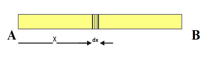
Mass of the small element dx,  dm= \lambda\ dx

dm= \lambda_o \;x dx
By integrating on both sides, we can calculate total mass of the rod
M= \int_0^L\;dm\;=\int_0^L\;\lambda_o\;x\;dx
M=\lambda_o\;\int_0^L\;\;x\;dx

 M=\lambda_o\;\left|\frac{x^2}2\right|_0^L=\;\frac12\lambda_o\;L^2….(2)

Now, we have to calculate , \int_0^Ldm\;x\;
\int_0^Ldm\;x\;=\;\int_0^L\;\lambda_o x\;dx\;x\;
\Rightarrow\int_0^Ldm\;x\;=\;\;\lambda_o\int_0^L\;x^2\;dx\;
\Rightarrow\;\int_0^Ldm\;x\;=\;\;\lambda_o\;\left|\frac{x^3}3\right|_0^L=\;\;\frac{\;\lambda_o\;L^3}3

 \Rightarrow\;\int_0^Ldm\;x\; =\;\;\frac{\;\lambda_o\;L^3}3….(3)

 From(1),(2)and (3)

x_{com}=\frac{\int_0^Ldm\;x}M\;=\frac{\frac{\;\lambda_o\;L^3}3}{\frac{\;\lambda_o\;L^2}2}\;
\Rightarrow\;x_{com}=\frac23L
Moment of Inertia of Rod having non-uniform, linearly increasing mass density
According to Parallel axis theorem ,
I_{parallel\;\;}=\;I_{COM}\;+\;M_{total\;}\;d^2
I_{O\;\;}=\;I_{C}\;+\;M \;(OC)^2
I_{B\;\;}=\;I_{C}\;+\;M \;(BC)^2
I_{A\;\;}=\;I_{C}\;+\;M \;(AC)^2
AC = 2L/3 , BC = L/3, OC= L/6
As, AC > BC> OC
Hence, I_A> I_B>I_O> I_C
(D) is correct option

Conclusion-

In case of variable mass density total mass  can be calculated by integration. And apply formula x_{com}=\;\frac{\int dm\;x}{\int dm} to find position/coordinate of  center of mass. Understanding of parallel axis theorem is key concept which relates all moment of inertias about any parallel axis with axis passing through centre of mass. Distribution of mass away from axis of rotation leads to greater value of moment of inertia about that axis.

A ball of mass m moving at a sped v makes a head on collision with an identical ball at rest. If the kinetic energy of the balls after collision is [latex]\frac34th[/latex] of the original. Then the coefficient of restitution is

head on collision in mechanics

Head on collision : Important case of partial elastic collision

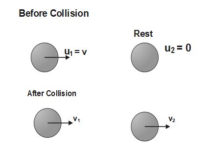
Q.A ball of mass m moving at a speed v makes a head on collision with an identical ball at rest. If the kinetic energy of the balls after collision is \frac34th of the original. Then the coefficient of restitution is

(A) e=\frac1{\sqrt2}

(B) e=\frac12

(C) e=\frac{\sqrt2}3

(D) e=\frac13

Solution

Key concepts to solve the following problem:

  • Head-on collision 
  • Coefficient of restitution
  • Conservation of linear momentum  
Given that, mass of each ball = m
According to law of conservation of momentum
m_1 u_1 +m_2 u_2 = m_1 v_1 + m_2 v_2
m v +m *0 = m v_1 + m v_2
m v = m (v_1 + v_2)
v = (v_1 + v_2)
v_1 + v_2 = v.....(1)
Given that , K.E._{net,f\;}=\frac34K.E._{net,i\;}
Therefore, \frac12\;m_1\;v_1^2\;+\;\frac12\;m_2\;v_2^2\;=\;\frac34\left[\frac12\;m_1\;u_1^2\;+\;\frac12\;m_2\;u_2^2\;\right]
\frac12\;m\;\left(\frac{v(1-e)}2\right)^2\;+\;\frac12\;m\;\left(\frac{v(1+e)}2\right)^2\;=\;\frac34\left[\frac12\;m\;v^2\;+\;\frac12\;m\;{\ast\;0}^2\;\right]
\frac12\;\;\frac{v^2\;\left(1+e\right)^2}4\;+\;\frac12\;\;\frac{v^2\;\left(1-e\right)^2}4\;=\;\frac34\left(\frac12\;v^2\;\right)
\Rightarrow\left(1+e\right)^2+\left(1-e\right)^2=3
\Rightarrow1+\;e^2+\;2e\;+\;1\;+\;e^2-2e\;= 3
\Rightarrow\;2\;e^2=\;1
\Rightarrow\;e^2=\;\frac12
\Rightarrow\;e=\;\frac1{\sqrt2}
(A) is correct option
head on collision in mechanics
The formula of coefficient of restitution is :
e=\;\frac{vel. of sepration}{vel. of approach}
e=\;\frac{v_2-v_1}{u_1-u_2}
e=\;\frac{v_2-v_1}{v-0}
v_2- v_1= ev ....(2)
On adding (1) and (2), we get
2 v_2 = v +ev
v_2=\;\frac{v(1+e)}2
On subtracting (2) from (1), we get
2 v_1 = v - ev
v_1=\;\frac{v(1-e)}2

Before jumping into the concept of head-on collisions partial elastic collision, we have to grasp a basic understanding of lines of impact and motion. Secondly, the knowledge of coefficient of restitution is of equal importance. 
  
Line of Impact:
The line along which the colliding objects make contact during the collision.

Line of Motion: The line along which the objects are moving.

Collisions can be classified into two main types based on the orientation of the line of impact and the line of motion of the colliding objects. These types are:

  1. Head on Collision :

    • In a head on collision, the line of impact is along the line of motion of the colliding objects. The objects approach each other directly, and the impact occurs along the same straight line. This type of collision is often analyzed in the context of one-dimensional motion for simplicity.
  2. Oblique Collision :

    • In an oblique collision, the line of impact is not aligned with the line of motion of the colliding objects. The objects approach each other at an angle, resulting in an impact that is not directly along the line of motion. Oblique collisions are more complex to analyze compared to head-on collisions, as they involve vector components and require consideration of two-dimensional motion.

Coefficient of Restitution:

The coefficient of restitution (e) is a crucial factor in understanding the nature of a collision. It is defined as the ratio of the final relative velocity of separation to the initial relative velocity of approach. Mathematically, e is expressed as:

e=\;\frac{relative\;velocity\;of\;separation}{relative\;velocity\;of\;appraoch\;}

The coefficient of restitution can take values between 0 and 1, inclusively, where:

  • represents a perfectly inelastic collision, where the colliding objects stick together after the collision. Here, the loss in net Kinetic energy is maximum after collision. And It is not necessary that there is always a complete loss of kinetic energy

 
  • denotes a partially elastic collision, where some of kinetic energy is lost. 

 
  • signifies a perfectly elastic collision, where the colliding objects bounce off each other without any loss of kinetic energy.

Conclusion:

Problem solving becomes easy if we have basic knowledge of types of collisions.  Understanding the coefficient of restitution is crucial in analyzing the nature of collisions and predicting the post-collision velocities of the objects involved. Except for perfectly inelastic collisions, the colliding objects get separated after the collision, undergoing either some loss or no loss in net kinetic energy, depending on the nature of the collision. Moreover, the law of conservation is applicable in all types of collisions, whether elastic, inelastic, or partially elastic