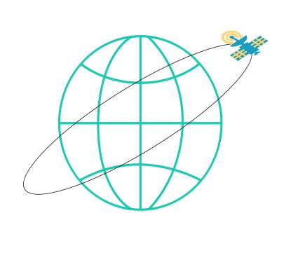
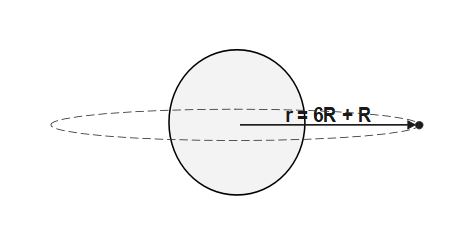
A spaceship is launched into a circular orbit close to the earth’s surface. What additional velocity has now to be imparted to the spaceship in the orbit to overcome the gravitational pull.

Additional velocity

Additional Velocity Required to Overcome Earth's Gravitational Pull for Satellite Escape

Escape velocity is the minimum velocity an object must attain to break free from the gravitational attraction of a massive body without further propulsion. For an object on the surface of the Earth, this velocity is approximately 11.2 kilometers per second (or about 25,000 miles per hour). But for a satellite already in orbit, the calculation is little more complex.

Satellites in low Earth orbit (LEO) typically travel at speeds around 8 kilometers per second (km/s). This velocity, known as orbital velocity, is necessary to counteract the gravitational force pulling the satellite towards Earth, allowing it to maintain a stable orbit.

However, what if we seek to free a satellite from Earth’s gravitational grasp altogether? Escaping Earth’s gravitational influence requires imparting additional velocity to the satellite. Suppose we have a satellite orbiting near the Earth’s surface, with an orbital velocity of approximately 8 km/s. To break free from Earth’s gravity, an additional velocity of approximately 3.2 km/s is needed.

Example

Q.A spaceship is launched into a circular orbit close to the earth's surface. What additional velocity has now to be imparted to the spaceship in the orbit to overcome the gravitational pull. Radius of earth =6400 km , g= 9.8 ms^{-2}

(A) 3.2 km/s

(B) 11.2 km/s

(C) 1.5 km/s

(D) 8 km/s

Solution

We know that , orbital speed of satellite is
v_o=\;\sqrt{\frac{GM}r}\;
where\;r\;is\;dis\tan ce\;from\;centre\;of\;planet/earth
Also, r= R+ h where R is radius of planet/earth and h is height of satellite from surface of earth
v_o=\;\sqrt{\frac{GM}{R+h}}\;
Near to earth's surface, h can be neglected
So, R\;+\;h\;\approx\;R
v_o=\;\sqrt{\frac{GM}{R}}\;
v_o=\;\sqrt{\frac{gR^2}{R}}\;
v_o=\;\sqrt{gR}\;
v_o\;=\;\sqrt{Rg}\approx\;8\;km/s\;
v_e\;=\;\sqrt{2Rg}\approx\;11.2\;km/s\;
Addition velocity required is
v_{add}\;=\;v_e\;\;-\;v_{o\;}
v_{add}\;=11.2 - 8 = 3.2 km/sec
(A) is correct option
Additional velocity

Conclusion

This additional velocity is crucial for overcoming the gravitational potential energy barrier that binds the satellite to Earth. When the satellite reaches this escape velocity, its kinetic energy surpasses the gravitational potential energy, allowing it to break away from orbit and venture into interplanetary space.
Kepler’s law of period

Kepler's law of period

Kepler's law of period for planetary motion

According to Kepler’s laws  of period for planetary motion, the square of the period of revolution of as planet around the sun is directly proportional to the cube of the semi-major axis of its orbit.

Mathematically, it can be expressed as T^2 = k a^3 , where is the orbital period of the planet, is the semi-major axis of its orbit, and is a constant that is the same for all planets orbiting the Sun. 

Example

Q.A geostationary satellite is orbiting the earth at a height of 6R above the surface of earth where R is the radius of earth. The time period of another satellite at a distance of 3.5 R from the centre of earth is

(A) 16.96 hours

(B) 8.48 hours

(C) 9.25 hours

(D) 15.76 hours

Solution

We know that , orbital speed of satellite is
v_o=\;\sqrt{\frac{GM}r}\;
where\;r\;is\;dis\tan ce\;from\;centre\;of\;planet/earth
T\;=\frac{dis\tan ce\;}{speed}=\;\frac{2\pi\;r}{v_o}
T\;=\;\frac{2\pi\;r}{\sqrt{\displaystyle\frac{GM}r}}
T\;=\;2\pi\;\sqrt{\frac{r^3}{GM}}
T\;=\;2\pi\;\sqrt{\frac{r^3}{GM}}\\T^2=\;4\;\pi^2\;\frac{r^3}{GM}
\Rightarrow T^2\;\;\propto\;r^3
This is known as Kepler's Law of period for planetary motion
r= R+ h where R is radius of planet/earth and h is height of satellite from surface of earth
\Rightarrow r_1 = R+ 6R=7R \;and \;r_2= 3.5R
\Rightarrow T\;\propto\;r^\frac32
\frac{T_2}{T_1}=\;\left(\frac{r_2}{r_1}\right)^\frac32
\frac{T_2}{T_1}=\;\left(\frac{3.5R}{7R}\right)^\frac32
\frac{T_2}{T_1}=\;\left(\frac{1}{2}\right)^\frac32
\frac{T_2}{T_1}=\frac1{2\sqrt2}
T_2 =T_1 * \frac1{2\sqrt2}
T_2 =24 * \frac1{2\sqrt2}
T_2 =12* \frac1{\sqrt2}
T_2 =12* 0.707= 8.48 \;hours
(B) is correct option

Conclusion

Kepler’s third law is also known as law of period which helps us to find the time period of orbital motion for various distances from sun. It includes following  applications. 

  1. Predicting Planetary Motion: Kepler’s law of periods allows astronomers to predict the orbital periods of planets based on their distances from the sun. This law has been crucial in the study of our solar system and in the discovery and characterization of exoplanets in other solar systems.

  2. Comparing Orbits: By comparing the orbital periods and semi-major axes of different planets or moons, astronomers can gain insights into the structure and dynamics of planetary systems. For example, comparing the orbital periods of moons around a planet can provide information about their relative distances from the planet.

  3. Verification of Kepler’s Laws: Kepler’s laws of planetary motion played a significant role in the development of Newton’s law of universal gravitation and the laws of motion. They served as a crucial test for Newtonian physics and provided evidence for the gravitational force between celestial bodies.
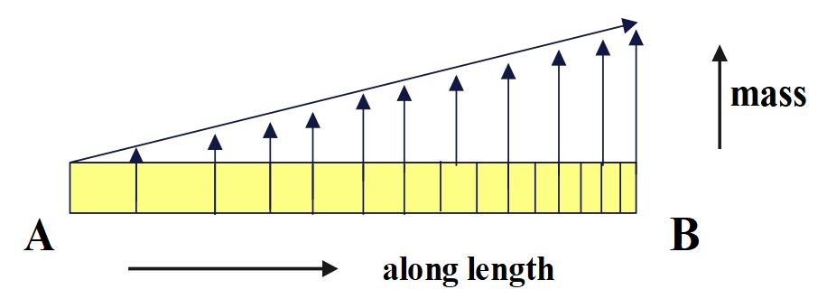
Moment of Inertia of a Rod having non-uniform, linearly increasing mass density

Moment of Inertia of Rod having non-uniform, linearly increasing mass density

Moment of Inertia of Rod having non-uniform, linearly increasing mass density

Moment of Inertia

Moment of inertia is of great importance when we come to discuss the rotational dynamics. The the word “inertia” refers to resistance against any change in state of object (mass). Specifically, the moment of inertia is measure of a body’s resistance to changes in its rotation. The greater the value of moment of inertia, the more is difficulty it is to cause change in its rotation.

The moment of inertia is often denoted as “I” and it is analogous to mass (m) of the object. In linear motion, mass quantifies an object’s resistance to linear acceleration (change in velocity) in response to a force. Similarly, in rotational motion, the moment of inertia quantifies an object’s resistance to angular acceleration (change in angular velocity) in response to a torque. Moreover, both are scalar quantities.  

Factors affecting Moment of Inertia

Here are the main factors affecting the moment of inertia:

  • Mass Distribution

  • Shape of the Object

  • Axis of Rotation

  • Size and Dimensions

  • Symmetry

Infact, we can can generalize the above all factor into one key factor – the mass distribution of body about axis of rotation which incorporates he definition of moment of inertia. 

I= m_1 r_1^{2} + m_2 r_2^{2}+ …… m_n r_n^{2} . Lets consider following example to grasp the concept of moment of inertia.

Example - On Moment of Inertia of Rod

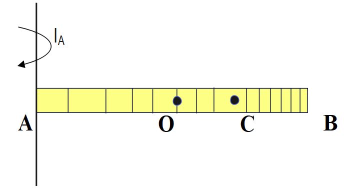
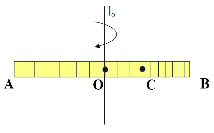
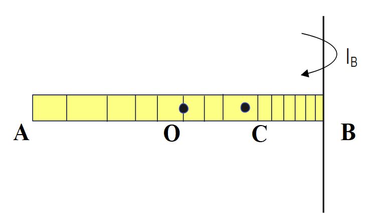
The density of a rod AB increases linearly from A to B. Its mid-point is O and centre of mass is at C. Four axes pass through A, B, O and C , all perpendicular to the length of rod. The moments of inertia of the rod about these axes are I_{A}, I_{B}, I_{O} and I_{C} respectively. Then
(A)I_{A}> I_{B}
(B)I_{C}< I_{B}
(C)I_{O}> I_{C}
(D) All of these

Solution

 The mass distribution of body about axis of rotation determine the value of moment of inertia.

I= m_1 r_1^{2} + m_2 r_2^{2}+ …… m_n r_n^{2}

If the overall mass is distributed nearer to axis of rotation then M.O.I. of the object(rigid body) will be smaller. And if mass is distributed away from axis of rotation it results into larger M.O.I. 

Moment of Inertia of Rod having non-uniform, linearly increasing mass density
Let us first locate the center of mass (C.O.M.) of the rod by using formula:
x_{com}=\;\frac{\int dm\;x}{\int dm}=\frac{\int dm\;x}M

\\x_{com}=\;\frac{\int_0^Ldm\;x}{\int_0^Ldm}=\frac{\int_0^Ldm\;x}M ….(1)

Given that ,the linear mass density of the rod varies linearly along the length as \lambda\;=\lambda_o\;x
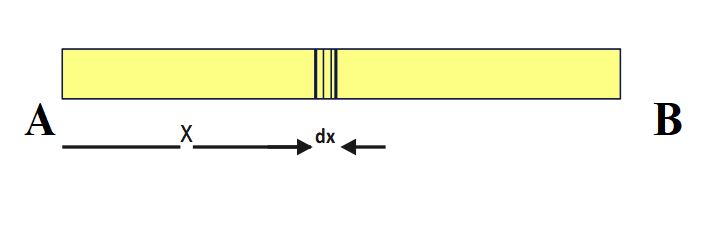
Mass of the small element dx,  dm= \lambda\ dx

dm= \lambda_o \;x dx
By integrating on both sides, we can calculate total mass of the rod
M= \int_0^L\;dm\;=\int_0^L\;\lambda_o\;x\;dx
M=\lambda_o\;\int_0^L\;\;x\;dx

 M=\lambda_o\;\left|\frac{x^2}2\right|_0^L=\;\frac12\lambda_o\;L^2….(2)

Now, we have to calculate , \int_0^Ldm\;x\;
\int_0^Ldm\;x\;=\;\int_0^L\;\lambda_o x\;dx\;x\;
\Rightarrow\int_0^Ldm\;x\;=\;\;\lambda_o\int_0^L\;x^2\;dx\;
\Rightarrow\;\int_0^Ldm\;x\;=\;\;\lambda_o\;\left|\frac{x^3}3\right|_0^L=\;\;\frac{\;\lambda_o\;L^3}3

 \Rightarrow\;\int_0^Ldm\;x\; =\;\;\frac{\;\lambda_o\;L^3}3….(3)

 From(1),(2)and (3)
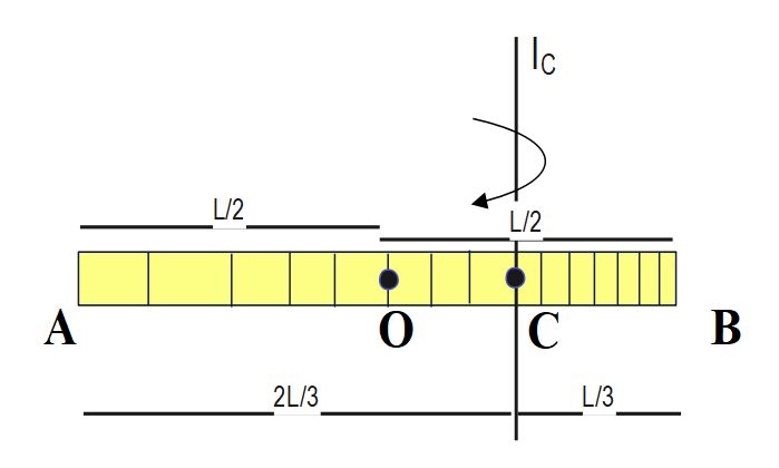
x_{com}=\frac{\int_0^Ldm\;x}M\;=\frac{\frac{\;\lambda_o\;L^3}3}{\frac{\;\lambda_o\;L^2}2}\;
\Rightarrow\;x_{com}=\frac23L
Moment of Inertia of Rod having non-uniform, linearly increasing mass density
According to Parallel axis theorem ,
I_{parallel\;\;}=\;I_{COM}\;+\;M_{total\;}\;d^2
I_{O\;\;}=\;I_{C}\;+\;M \;(OC)^2
I_{B\;\;}=\;I_{C}\;+\;M \;(BC)^2
I_{A\;\;}=\;I_{C}\;+\;M \;(AC)^2
AC = 2L/3 , BC = L/3, OC= L/6
As, AC > BC> OC
Hence, I_A> I_B>I_O> I_C
(D) is correct option

Conclusion-

In case of variable mass density total mass  can be calculated by integration. And apply formula x_{com}=\;\frac{\int dm\;x}{\int dm} to find position/coordinate of  center of mass. Understanding of parallel axis theorem is key concept which relates all moment of inertias about any parallel axis with axis passing through centre of mass. Distribution of mass away from axis of rotation leads to greater value of moment of inertia about that axis.
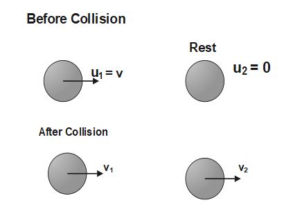
A ball of mass m moving at a sped v makes a head on collision with an identical ball at rest. If the kinetic energy of the balls after collision is [latex]\frac34th[/latex] of the original. Then the coefficient of restitution is

head on collision in mechanics

Head on collision : Important case of partial elastic collision

Q.A ball of mass m moving at a speed v makes a head on collision with an identical ball at rest. If the kinetic energy of the balls after collision is \frac34th of the original. Then the coefficient of restitution is

(A) e=\frac1{\sqrt2}

(B) e=\frac12

(C) e=\frac{\sqrt2}3

(D) e=\frac13

Solution

Key concepts to solve the following problem:

  • Head-on collision 
  • Coefficient of restitution
  • Conservation of linear momentum  
Given that, mass of each ball = m
According to law of conservation of momentum
m_1 u_1 +m_2 u_2 = m_1 v_1 + m_2 v_2
m v +m *0 = m v_1 + m v_2
m v = m (v_1 + v_2)
v = (v_1 + v_2)
v_1 + v_2 = v.....(1)
Given that , K.E._{net,f\;}=\frac34K.E._{net,i\;}
Therefore, \frac12\;m_1\;v_1^2\;+\;\frac12\;m_2\;v_2^2\;=\;\frac34\left[\frac12\;m_1\;u_1^2\;+\;\frac12\;m_2\;u_2^2\;\right]
\frac12\;m\;\left(\frac{v(1-e)}2\right)^2\;+\;\frac12\;m\;\left(\frac{v(1+e)}2\right)^2\;=\;\frac34\left[\frac12\;m\;v^2\;+\;\frac12\;m\;{\ast\;0}^2\;\right]
\frac12\;\;\frac{v^2\;\left(1+e\right)^2}4\;+\;\frac12\;\;\frac{v^2\;\left(1-e\right)^2}4\;=\;\frac34\left(\frac12\;v^2\;\right)
\Rightarrow\left(1+e\right)^2+\left(1-e\right)^2=3
\Rightarrow1+\;e^2+\;2e\;+\;1\;+\;e^2-2e\;= 3
\Rightarrow\;2\;e^2=\;1
\Rightarrow\;e^2=\;\frac12
\Rightarrow\;e=\;\frac1{\sqrt2}
(A) is correct option
head on collision in mechanics
The formula of coefficient of restitution is :
e=\;\frac{vel. of sepration}{vel. of approach}
e=\;\frac{v_2-v_1}{u_1-u_2}
e=\;\frac{v_2-v_1}{v-0}
v_2- v_1= ev ....(2)
On adding (1) and (2), we get
2 v_2 = v +ev
v_2=\;\frac{v(1+e)}2
On subtracting (2) from (1), we get
2 v_1 = v - ev
v_1=\;\frac{v(1-e)}2

Before jumping into the concept of head-on collisions partial elastic collision, we have to grasp a basic understanding of lines of impact and motion. Secondly, the knowledge of coefficient of restitution is of equal importance. 
  
Line of Impact:
The line along which the colliding objects make contact during the collision.

Line of Motion: The line along which the objects are moving.

Collisions can be classified into two main types based on the orientation of the line of impact and the line of motion of the colliding objects. These types are:

  1. Head on Collision :

    • In a head on collision, the line of impact is along the line of motion of the colliding objects. The objects approach each other directly, and the impact occurs along the same straight line. This type of collision is often analyzed in the context of one-dimensional motion for simplicity.
  2. Oblique Collision :

    • In an oblique collision, the line of impact is not aligned with the line of motion of the colliding objects. The objects approach each other at an angle, resulting in an impact that is not directly along the line of motion. Oblique collisions are more complex to analyze compared to head-on collisions, as they involve vector components and require consideration of two-dimensional motion.

Coefficient of Restitution:

The coefficient of restitution (e) is a crucial factor in understanding the nature of a collision. It is defined as the ratio of the final relative velocity of separation to the initial relative velocity of approach. Mathematically, e is expressed as:

e=\;\frac{relative\;velocity\;of\;separation}{relative\;velocity\;of\;appraoch\;}

The coefficient of restitution can take values between 0 and 1, inclusively, where:

  • represents a perfectly inelastic collision, where the colliding objects stick together after the collision. Here, the loss in net Kinetic energy is maximum after collision. And It is not necessary that there is always a complete loss of kinetic energy

 
  • denotes a partially elastic collision, where some of kinetic energy is lost. 

 
  • signifies a perfectly elastic collision, where the colliding objects bounce off each other without any loss of kinetic energy.

Conclusion:

Problem solving becomes easy if we have basic knowledge of types of collisions.  Understanding the coefficient of restitution is crucial in analyzing the nature of collisions and predicting the post-collision velocities of the objects involved. Except for perfectly inelastic collisions, the colliding objects get separated after the collision, undergoing either some loss or no loss in net kinetic energy, depending on the nature of the collision. Moreover, the law of conservation is applicable in all types of collisions, whether elastic, inelastic, or partially elastic
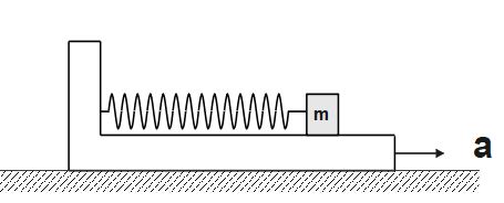
What is the maximum compression in the spring, if the lower block is shifted to rightward with acceleration a. (Given that all surfaces are smooth as shown).

What is the maximum compression in the spring, if the lower block is shifted to rightward with acceleration a. (Given that all surfaces are smooth as shown).

Maximum compression in the spring

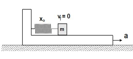
Q.What is the maximum compression in the spring, if the lower block is shifted to rightward with acceleration a. (Given that all surfaces are smooth as shown).

What is the maximum compression in the spring, if the lower block is shifted to rightward with acceleration a. (Given that all surfaces are smooth as shown).

(A) \frac{ma}k

(B) \frac{2ma}k

(C) \frac{mak}2

(D) \frac{ma}{2k}
Solution

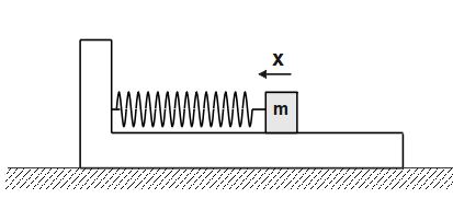
Let us assume that the upper block of mass 'm' displaces by distance 'x' towards leftward with velocity 'v' (w.r.t to lower block) when lower block is shifted towards rightward with acceleration a.

We can solve this problem by two methods (1) Force Method (2) Energy Method from non-inertial frame of reference (Lower plank/block) .

Force Method

Acc. to Newton's 2nd law of motion,
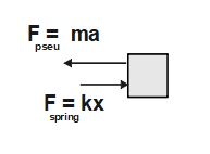
F_{net}=F_{pseu}-F_{spring}
F_{net}=ma- kx
m a_1 =ma- kx
m \frac{\operatorname dv}{\operatorname dt}=ma\;-\;kx
mv\frac{\operatorname dv}{\operatorname dx}=ma\;-\;kx
mv\;dv=\left(ma\;-\;kx\right)\;dx
Integrating both sides
m \int_{v_i}^{v_f}\;vdv=\int_{x_i}^{x_f}\left(ma\;-\;kx\right)\;dx
m\int_{0}^{0}\;vdv=\int_{0}^{x_o}\left(ma\;-\;kx\right)\;dx
m\left[\frac{v^2}2\right]_0^0=\;ma\;\left[x\right]_0^{x_0}-k\left[\frac{x^2}2\right]_0^{x_o}
m(0-0)=\;ma\;\left(x_o-0\right)-\;\frac12k\;\left(x_o^2-0\right)
0=\;ma x_o - \;\frac12k\ x_o^2
ma x_o = \frac12k\ x_o^2
2ma= k x_{o}
x_o=\frac{2ma}k
(B) is correct option
let a_1 be the acceleration of upper block w.r.t the lower block
FBD of upper block from lower block reference frame
Q3.What is the maximum compression in the spring, if the lower block is shifted to rightward with acceleration a. (Given that all surfaces are smooth as shown).
Boundary conditions for integration:
What is the maximum compression in the spring, if the lower block is shifted to rightward with acceleration a. (Given that all surfaces are smooth as shown).
Initially, the upper block is at rest when x=0, therefore v_{i}=0
When the spring has maximum compression x_{o}, again the block becomes stationary w.r.t. lower block.
So, v_{f}=0 , when x=x_{o}

Alternate Method

We can also solve this problem by Energy Method from non-inertial frame of reference (Lower plank/block) . We will apply Work-Energy theorem from lower block frame of reference.

Energy Method

We can apply Work-Energy theorem for initial and final positions of upper block w.r.t. lower block
What is the maximum compression in the spring, if the lower block is shifted to rightward with acceleration a. (Given that all surfaces are smooth as shown).
Since, at initial position the upper block is at rest, therefore v_{i}=0
When the spring has maximum compression x_{o}, again the block becomes stationary w.r.t. lower block. So, also v_{f}=0
Acc. to Work-Energy Theorem,
W.D_{net \;by\;all\;forces}\;=\triangle K.E.\;
W.D._{pseudo}\;\;+\;W.D._{spring}\;=\;\frac12m\;v_f^2-\frac12m\;v_i^2
W.D._{pseudo}\;\;+\;W.D._{spring}\;=\;\frac12m\;*0^2-\frac12m\;*0^2
\Rightarrow\;ma\;x_o-\;\frac12k\;x_o^2=0
\Rightarrow\;ma\;x_o=\;\frac12k\;x_o^2
\Rightarrow\;ma\;=\;\frac12k\;x_o
\Rightarrow\;x_o=\frac{2ma}k
(B) is correct option
\;W.D._{cons}\;=-\triangle U
\;\Rightarrow\;W.D._{spring}\;=-\triangle U
\;\Rightarrow W.D._{spring}\;=-\;\frac12k\;x_{o}^2
And, W.D._{pseu}={\overrightarrow{F\;}}_{pseu}.\overrightarrow{x_o}
\Rightarrow W.D._{pseu}=F_{pseu}\;x_{o\;}\cos0^o
\Rightarrow W.D._{pseu}=ma\;x_{o\;}

Key concept to solve above problem

 
  • Frame of reference 
  • Pseudo force
  • Work-Energy Theorem
  • Condition for Maximum compression in the spring
Frame of reference

In mechanics , the frame of reference is directly tied to the perspective of an observer.  A frame of reference is essentially a set of coordinate axes and a set of observational rules that allow an observer to quantify and describe the motion of objects. The observer’s point of view or choice of reference frame influences how the physical phenomena are described and analyzed. All of us know that the motion is a relative concept. So, frame of reference which observer chooses directly affect the observation. 

For example, if you are driving to towards Taj Mahal and after some time a fellow passenger ask when will Taj Mahal come whereas he knows you are moving towards destination!
It does indeed reflect a perspective from the car’s frame of reference. The passenger is implicitly treating the car as the stationary reference point, making it appear as though the Taj Mahal is approaching them. From the frame of reference inside the car, the surroundings outside might seem to be moving, creating the perception that the destination (Taj Mahal) is approaching. Meanwhile, from an external frame of reference, such as someone on the ground, it would be clear that the car is moving towards the stationary Taj Mahal.

Let’s consider the other (following) example which helps you to grasp the concept. 

If you are inside a car moving at a constant speed and you throw a ball straight up, from your perspective inside the car, the ball will appear to go straight up and down. However, an observer outside the car, seeing the entire motion, would notice that the ball follows a parabolic trajectory due to the combined motion of the car and the ball. There are mainly two type of frame of references


(1)
Inertial Frame of Reference:

  • An inertial frame of reference is often preferred when studying the laws of mechanics. In an inertial frame, an object either remains at rest or moves with a constant velocity unless acted upon by an external force.
  • Newton’s laws of motion are formulated with respect to inertial frames.
(2) Non-Inertial Frames:
  • In non-inertial frames (accelerating or rotating frames), additional forces called fictitious forces may appear. These forces are not “real” forces but are necessary for describing motion accurately from the perspective of an observer in a non-inertial frame.
  • Common example include centrifugal
Pseudo force 

A pseudo force is an apparent or fictitious force introduced in non-inertial reference frames to account for observed accelerations, allowing the application of Newton’s laws of motion as if the frame were inertial.

Work Energy Theorem

The work-energy theorem states that the work done on an object  by all forces (conservative, non conservative, pseudo force etc. ) is equal to the change in its kinetic energy. In equation form, it can be expressed as:

�=��

Condition for maximum compression in the spring

When a block is attached to a spring and compressed to its maximum, the block will momentarily come to rest with respect to the reference frame  to which the spring is attached., assuming no external forces act on the block after it reaches its maximum compression.

When the spring is compressed to its maximum, the potential energy stored in the spring is at its maximum, and this energy is then converted into kinetic energy as the block is released. At the point of maximum compression, the block’s velocity becomes zero before it starts moving in the opposite direction due to the restoring force of the spring. The momentary pause at maximum compression in the spring, is indeed a point where the block stops with respect to the frame to which the spring is attached.

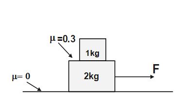
For given system of two blocks, find the maximum value of force F which can be applied on the system as shown in figure so that both blocks move together. [Given coefficient of static friction between both blocks = 0.3]

static friction to move two blocks together for IIT-JEE and NEET

How Static Friction helps two blocks to move together !

Q.For given system of two blocks, find the maximum value of force F which can be applied on the system as shown in figure so that both blocks move together. [Given coefficient of static friction between both blocks = 0.3]

(A) 3N

(B) 6N

(C) 9N

(D) 12N

static friction to move two blocks together for IIT-JEE and NEET

Solution

Free body diagram of block of upper block is

For given system of two blocks, find the maximum value of force F which can be applied on the system as shown in figure so that both blocks move together. [Given coefficient of static friction between both blocks = 0.3]
We can see that the block 1 Kg (upper block) is moved by friction force. If block moves together (without slipping) it means the frictional force is static friction. Therefore,
f_{s,max}=\;\mu_sN
f_{s,max}=\;\mu_s mg
f_{s,max}=\;\ 0.3 * 1 * 10 = 3N
Thus, maximum acceleration that can be produced in upper block without slipping is
a_{max}=\frac{f_{s,max}}m=\;\frac31=3ms^{-2}
For system of blocks , to move together the maxmium force can be
F_{max}=\;M_{sys,net\;}\ast\;\;a_{max}
F_{max}=(1+2) * 3= 9N
(C) is correct option

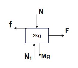
In the above example, we can notice clearly that lower block is acted upon by applied (in forward direction) force which causes the motion in lower block [see free body diagram given below].But, the question arises how the upper block is moving in forward direction despite being no direct force on it? What force is there that moves the upper block? The obvious answer is, the friction, which drives the upper block in same direction. Many students might think that how friction can cause motion, as they feel the friction only opposes the motion. Infact , it is a only a misconception that many student grasp due to incomplete knowledge of concept of friction.
Friction necessarily opposes relative motion (sliding) between two contact surfaces, and also some times supports the motion of one object (w.r.t. other frame) while opposing relative motion of one surface over other. When there is no actual relative motion (sliding) between two contact surfaces but exists only the tendency of sliding one surface over the other, then, the frictional force acting between the contact surfaces is static friction. The static friction, as the name says, acts to keep the surface in contact (stationary w.r.t. each other)  by stopping the sliding motion between them. To move both blocks together as in the above example, static friction provides the acceleration to upper block while opposing the lower block at the same time so that there is no sliding between them. The acceleration will be maximum when maximum static friction (limiting friction) comes into play. The limiting friction can be calculated by the formula 
f_{s,max}=\;\mu_sN

Using the maximum value of acceleration, the maximum force value can be easily found out. We have,

F_{max}=\;M_{sys,net\;}\ast\;\;a_{max}

F.B.D. of lower block

F.B.D. of upper block

For given system of two blocks, find the maximum value of force F which can be applied on the system as shown in figure so that both blocks move together. [Given coefficient of static friction between both blocks = 0.3]

Conclusion-

Friction plays an essential role in motion despite being a dissipative force. It generally dissipates energy; however, sometimes it utilizes a portion of it to provide kinetic energy to other systems or its own subsystems. In the present case, friction provides kinetic energy to the upper block and performs positive work. Of course, the overall work done by friction is negative. A free-body diagram is necessary for a clear understanding of all forces.

The direction of friction is simply determined by Newton’s third law of motion. It is generally taken in the opposite direction to the applied force on one body (the lower block in this case), i.e., in the backward direction. The direction of friction acting on the other body (the upper block in this case), according to Newton’s third law, will be in the forward direction, just opposite to that of the lower block.

Friction is a contact force. Static friction comes into action until the applied force becomes sufficient to initiate sliding between the contact surfaces. There are also limiting values for static friction because, up to a certain maximum, it tends to prevent actual relative motion, and eventually, sliding begins beyond the limiting friction. Thus, static friction disappears, and kinetic friction comes into play.

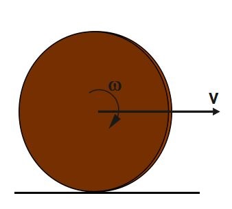
A solid disc is rolling without slipping on a horizontal ground as shown in figure. Its total kinetic energy is 150 J . What are its translational and rotational kinetic energies respectively?

Rolling of a solid disc on horizontal and its K.E. energies Mechanics 10 Important Problems for IIT-JEE and NEET

Rolling of a solid disc on horizontal

Rolling , specifically a pure rolling is a classic example of combined translational and rotational motion. While talking about the rolling of a  solid disc over horizontal ground, actually we are discussing a simple case of rolling. Pure rolling refers rolling without slipping. Thus, there is no presence of kinetic friction between point of contact and horizontal surface. Kinetic friction keeps acting until pure rolling is achieved.  Static friction may or may not be present in the motion, it depends on on factor whether a force is present throughout the motion or not.        
 For permanent pure rolling(without slipping), we have conditions i.e.  v=\;R\omega and a=\;R\alpha
These are relations between angular speed and linear speed (angular acceleration and tangential acceleration) defines the situation of rolling without slipping.

Rolling of a solid disc on horizontal - A Case of Pure rolling

Here, we are considering an example which incorporates the concept of rolling of a solid disc on horizontal – a case of Pure rolling and its both kinetic energies- translational and rotational. Also, we can use these conditions (of rolling) to relate both kinetics energies of combined translational and rotational motion. 

Example - A solid disc is rolling without slipping on a horizontal ground as shown in figure. Its total kinetic energy is 150 J . Its translational and rotational kinetic energies respectively are

(A) 50 J , 100 J

(B)100 J , 50J

(C) 75 J, 75J

(D) 125J , 25J

Rolling of a solid disc on horizontal and its K.E. energies Mechanics 10 Important Problems for IIT-JEE and NEET

Solution

As we know that, for pure rolling(without slipping) v=\;R\omega
Rolling of a solid disc on horizontal and its K.E. energies Mechanics 10 Important Problems for IIT-JEE and NEET
\frac{K.E._R}{K.E_T}=\frac{{\displaystyle\frac12}I\;\omega^2}{{\displaystyle\frac12}m\;v^2}
\frac{K.E._R}{K.E_T}=\;\frac{\displaystyle\frac12\left(mK^2\right)\;\omega^2}{\displaystyle\frac12m\;v^2}
\frac{K.E._R}{K.E_T} =\frac{\displaystyle K^2\;\omega^2}{\displaystyle v^2}
\frac{K.E._R}{K.E_T}=\frac{\displaystyle K^2\;\omega^2}{\displaystyle{(R\omega)}^2}=\frac{\displaystyle K^2\;\omega^2}{\displaystyle R^2\;\omega^2}
\frac{K.E._R}{K.E_T}=\frac{\displaystyle K^2\;}{\displaystyle R^2\;}.......(1)
Now, I=\;\frac12m\;R^2=m\;K^2\; where\; K \;is \;radius\; of\; Gyration
\Rightarrow\frac{K^2}{R^2}=\frac12.......(2)
\Rightarrow\;\frac{K.E._R}{K.E_T}=\frac{K^2}{R^2}=\frac12 [from (1) and (2)]
\Rightarrow\;\frac{K.E._R}{K.E_T}=\frac12
\Rightarrow\ K.E_T=\;\left(\frac2{1+2}\right)\;K.E._{total}
\Rightarrow\ K.E_T=\;\left(\frac2{3}\right)\;*150
\Rightarrow\ K.E_T= 2* 50 = 100J
Similarly, K.E_R=\;\left(\frac1{1+2}\right)\;K.E._{total}
\Rightarrow K.E_R=\;\left(\frac1{1+2}\right)\;*150
\Rightarrow K.E_R=\;\left(\frac1{3}\right)\;*150
\Rightarrow K.E_R=1*50=50J
(B) is correct option

Conclusion: -

From above discussion , we can easily understand that the basic knowledge of moment of inertia, kinetic energies and condition of rolling (without slipping) helps us to solve problems based on such concepts. For more question visit the page Physics-XI Mechanics 

Count of Beats: How to determine the frequency of Unknown Tuning Fork

Count of Beats : How to determine the frequency of Unknown Tuning Fork

Count of Beats : How to determine the frequency of Unknown Tuning Fork

Count of Beats : How to determine the frequency of Unknown Tuning Fork

Beats is a popular word among musician. Using beats formation concept, they tune their instruments while playing them against some standard frequency. All instruments come into tune when beats disappear. Now the instruments sound with same standard frequency which implies that there has been a change or improvement in the way all the instruments are synchronized to achieve a uniform frequency.

Beat frequency can be simply termed as number of beats produced per second. Beat frequency can be easily calculated by formula :

f_{beat}=\;\left|f_1-f_2\right|

Here, f_{beat} is beat frequency (number of beats produced per second) and f_1 and f_2 are frequency of two different sounds/tuning forks.

For example, if two tuning forks have frequencies of 440 Hz and 442 Hz, the beat frequency would be \left|\;440-442\;\right|=2 beats per second. The human ear should be able to detect and perceive these two beats.


When the difference in frequencies between two sound sources is large, the resulting beats become less perceptible to the human ear. Beats are more pronounced and easily perceived when the frequency difference is smaller. As the frequency difference increases, the rate of beats also increases, but the individual beats become less distinguishable and may merge into a continuous, rapidly fluctuating sound.

The ability to perceive beats is not solely dependent on the numerical difference in frequencies but also on the overall frequency range and sensitivity of an individual’s hearing. In many cases, people can perceive beats with differences well below 10 Hz.

Determination of Unknown Frequency by using concept of Beats

beats formation
Count of Beats : How to determine the frequency of Unknown Tuning Fork

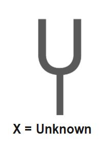
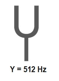
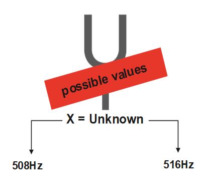
Lets us assume that we have two tuning forks Y and X . The frequency of Y is known to be 512Hz whereas the frequency of X is unknown. When Y is sounded with X it produces 4 beats per second.  

f_{beat}=\;\left|f_1-f_2\right| =4

 Using above formula and putting f_{1}= 512Hz , we can say that the possible values of frequencies of unknown tuning fork are 512-4\;=\;508\;Hz\;and\;512+4\;=516Hz

Count of Beats : How to determine the frequency of Unknown Tuning Fork

Now, it is to decide that which values is actual value of frequncy of unknown tuning fork X among  508Hz and  516Hz.

We have two method to assign correct value to unknown frequency X.

1.By Loading Unknown Tuning Fork (X) with wax

Loading of wax makes tuning fork heavier which leads to decrease in frequency. Thus, the frequency of unknown tuning fork X after loading wax, decreases. Let us say these decreased values are 507 Hz (for 508 Hz) and 515Hz ( for 516Hz).

Therefore, new possible beats when X (on loading) with decreased frequencies is sounded with Y are:  
Case-1:- \left|512-\;507\right|=\;5\; beats per second (note that beats increases in this case )

Case-2:- \left|512-\;515\right|=\;3\; beats per second (note that beats decreases in this case )

(a).On loading wax, again sound the unknown tuning fork X with Y, if beats increases as in case (1), then 508Hz is actual value of unknown frequency, X=508Hz

(b). On loading wax, again sound the unknown tuning fork X with Y, if beats decrease as in case (2), then 516 Hz is actual value of unknown frequency, X=516 Hz

Sample Question– Tuning fork A when sounded with a tuning fork B of frequency 480 Hz gives 5 beats per second. When the prongs of A are loaded with wax, it gives 3 beats per second. Find the original frequency of A.

Solution:-

Given that , known frequency (of fork B) = 480 Hz
Let Unknown frequency of fork A = x 

They produce beat when sounded together = 5

Therefore, possible values of x are 480- 5 = 475 Hz and 480+5 = 485 Hz
Now, we have to check  which value among 475Hz and 485Hz is correct?

As, this is a case of loading wax , therefore, frequency of A  (on loading wax) decreases. Hence, two possible values are  474 (say) and 484(say) respectively. 


Therefore, new possible beats when A (on loading) with decreased frequencies is sounded with B(480Hz) are:  

Case-1:- \left|480-\;474\right|=\;6\; beats per second (note that beats increase in this case )

Case-2:- \left|480-\;484\right|=\;4\; beats per second (note that beats decrease in this case )

It is already given that on loading fork B produces 3 beats per second with fork A which means beats per second are decreasing.
That is why we will chose the second case which shows decrease in beats per second. Finally, we assign 485 Hz as actual value of unknown fork A. 
Answer of this question is f_{A}= 485Hz

Questions for practice

Question 1 – A tuning fork of known frequency 440 Hz is sounded simultaneously with another tuning fork. The beat frequency observed is 4 Hz. When a small piece of wax is loaded onto the second tuning fork, the beat frequency becomes 2 Hz. Determine the frequency of the second tuning fork. 

Question-2  A tuning fork of unknown frequency is sounded simultaneously with another tuning fork of known frequency 450 Hz. The beat frequency observed is 5 Hz. To make the beats disappear, a small piece is filed from the prongs of the unknown tuning fork. After filing, the beat frequency reduces to 1 Hz. Determine the frequency of the unknown tuning fork before and after filing.

Now, you can try the above questions by yourself and send us the your answers. We would respond to answers in comment section. 

2.By Filing Unknown Tuning Fork (X)

If the prong of fork is filed a little, its mass gets reduced and its frequency increases. Therefore, frequency of filed unknown tuning fork X decreases. Suppose that increased values are 510Hz Hz (for 508 Hz) and 518Hz ( for 516Hz).

Therefore, new possible beats when X (filed) with increased frequencies is sounded with Y are:  
Case-1:- \left|512-\;510\right|=\;2\; beats per second (note that beats decreases in this case )

Case-2:- \left|512-\;518\right|=\;6\; beats per second (note that beats increases in this case )

(a).After filing, again sound the unknown tuning fork X with Y, if beats increases as in case (2), then 516Hz is actual value of unknown frequency, X=516Hz

(b). After filing, again sound the unknown tuning fork X with Y, if beats decrease as in case (1), then 508 Hz is actual value of unknown frequency, X=508 Hz

Sample QuestionA tuning fork P produces 8 beats per second with another tuning fork Q  of frequency 342Hz. When the prongs of the tuning fork P are filed a little, the number of beats produced per second decreases to 4. Find the frequency of the tuning fork P before filing its prongs.

Solution:-

Given that , known frequency (of fork Q) = 342 Hz
Let Unknown frequency of fork P = x 

They produce beat when sounded together before filing = 8

Therefore, possible values of x are 342- 8 = 334 Hz and 342+8 = 350 Hz
Now, we have to check  which value among 334Hz and 350Hz is actual frequency of P before filing?

As, this is a case of filing, therefore, frequency of P  (on filing) increases. Hence, two possible values are  337 (say) and 353(say) respectively. 


Therefore, new possible beats when P (after filing) with increased frequencies is sounded with Q(342 Hz) are:  

Case-1:- \left|342-\;337\right|=\;5\; beats per second (note that beats decrease in this case )

Case-2:- \left|342-\;353\right|=\;9\; beats per second (note that beats increase in this case )

It is already given that on loading fork B produces 4 beats per second with fork A which means beats per second are decrease.

That is why we will chose the first case which shows decrease in beats per second. Finally, we assign 334 Hz as actual value of unknown fork P. 
Answer of this question is f_{P}= 334Hz

10 Important Problems for IIT-JEE and NEET

10 Important Problems for IIT-JEE and NEET

Problems 1 of "10 Important Problems for IIT-JEE and NEET"

Q1.A solid disc is rolling without slipping on a horizontal ground as shown in figure. Its total kinetic energy is 150 J . Its translational and rotational kinetic energies respectively are

(A) 50 J , 100 J

(B)100 J , 50J

(C) 75 J, 75J

(D) 125J , 25J

Rolling of a solid disc on horizontal and its K.E. energies Mechanics 10 Important Problems for IIT-JEE and NEET

Solution

As we know that, for pure rolling(without slipping) v=\;R\omega
Rolling of a solid disc on horizontal and its K.E. energies Mechanics 10 Important Problems for IIT-JEE and NEET
\frac{K.E._R}{K.E_T}=\frac{{\displaystyle\frac12}I\;\omega^2}{{\displaystyle\frac12}m\;v^2}
\frac{K.E._R}{K.E_T}=\;\frac{\displaystyle\frac12\left(mK^2\right)\;\omega^2}{\displaystyle\frac12m\;v^2}
\frac{K.E._R}{K.E_T} =\frac{\displaystyle K^2\;\omega^2}{\displaystyle v^2}
\frac{K.E._R}{K.E_T}=\frac{\displaystyle K^2\;\omega^2}{\displaystyle{(R\omega)}^2}=\frac{\displaystyle K^2\;\omega^2}{\displaystyle R^2\;\omega^2}
\frac{K.E._R}{K.E_T}=\frac{\displaystyle K^2\;}{\displaystyle R^2\;}.......(1)
Now, I=\;\frac12m\;R^2=m\;K^2\; where\; K \;is \;radius\; of\; Gyration
\Rightarrow\frac{K^2}{R^2}=\frac12.......(2)
\Rightarrow\;\frac{K.E._R}{K.E_T}=\frac{K^2}{R^2}=\frac12 [from (1) and (2)]
\Rightarrow\;\frac{K.E._R}{K.E_T}=\frac12
\Rightarrow\ K.E_T=\;\left(\frac2{1+2}\right)\;K.E._{total}
\Rightarrow\ K.E_T=\;\left(\frac2{3}\right)\;*150
\Rightarrow\ K.E_T= 2* 50 = 100J
Similarly, K.E_R=\;\left(\frac1{1+2}\right)\;K.E._{total}
\Rightarrow K.E_R=\;\left(\frac1{1+2}\right)\;*150
\Rightarrow K.E_R=\;\left(\frac1{3}\right)\;*150
\Rightarrow K.E_R=1*50=50J
(B) is correct option

Problems 2 of "10 Important Problems for IIT-JEE and NEET"

Q2.For given system of two blocks, find the maximum value of force F which can be applied on the system as shown in figure so that both blocks move together. [Given coefficient of static friction between both blocks = 0.3]

(A) 3N

(B) 6N

(C) 9N

(D) 12N

static friction to move two blocks together for IIT-JEE and NEET

Solution

Free body diagram of block of upper block is

For given system of two blocks, find the maximum value of force F which can be applied on the system as shown in figure so that both blocks move together. [Given coefficient of static friction between both blocks = 0.3]
We can see that the block 1 Kg (upper block) is moved by friction force. If block moves together (without slipping) it means the frictional force is static friction. Therefore,
f_{s,max}=\;\mu_sN
f_{s,max}=\;\mu_s mg
f_{s,max}=\;\ 0.3 * 1 * 10 = 3N
Thus, maximum acceleration that can be produced in upper block without slipping is
a_{max}=\frac{f_{s,max}}m=\;\frac31=3ms^{-2}
For system of blocks , to move together the maxmium force can be
F_{max}=\;M_{sys,net\;}\ast\;\;a_{max}
F_{max}=(1+2) * 3= 9N
(C) is correct option

Problems 3 of "10 Important Problems for IIT-JEE and NEET"

Q3.What is the maximum compression in the spring, if the lower block is shifted to rightward with acceleration a. (Given that all surfaces are smooth as shown).

What is the maximum compression in the spring, if the lower block is shifted to rightward with acceleration a. (Given that all surfaces are smooth as shown).

(A) \frac{ma}k

(B) \frac{2ma}k

(C) \frac{mak}2

(D) \frac{ma}{2k}
Solution

Let us assume that the upper block of mass 'm' displaces by distance 'x' towards leftward with velocity 'v' (w.r.t to lower block) when lower block is shifted towards rightward with acceleration a.

We can solve this problem by two method (1) Force Method (2) Energy Method from non-inertial frame of refence (Lower plank/block) .

Force Method

Acc. to Newton's 2nd law of motion,
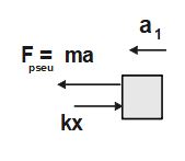
F_{net}=F_{pseu}-F_{spring}
F_{net}=ma- kx
\frac{\operatorname dv}{\operatorname dt}=ma\;-\;kx
v\frac{\operatorname dv}{\operatorname dx}=ma\;-\;kx
v\;dv=\left(ma\;-\;kx\right)\;dx
Integrating both sides
\int_{v_i}^{v_f}\;vdv=\int_{x_i}^{x_f}\left(ma\;-\;kx\right)\;dx
\int_{0}^{0}\;vdv=\int_{0}^{x_o}\left(ma\;-\;kx\right)\;dx
\left[\frac{v^2}2\right]_0^0=\;ma\;\left[x\right]_0^{x_0}-k\left[\frac{x^2}2\right]_0^{x_o}
0-0=\;ma\;\left(x_o-0\right)-\;\frac12k\;\left(x_o^2-0\right)
0=\;ma x_o - \;\frac12k\ x_o^2
ma x_o = \frac12k\ x_o^2
2ma= k x_{o}
x_o=\frac{2ma}k
(B) is correct option
let a_1 be the acceleration of upper block w.r.t the lower block
FBD of upper block from lower block reference frame
Q3.What is the maximum compression in the spring, if the lower block is shifted to rightward with acceleration a. (Given that all surfaces are smooth as shown).
Boundary conditions for integration:
What is the maximum compression in the spring, if the lower block is shifted to rightward with acceleration a. (Given that all surfaces are smooth as shown).
Initially, the upper block is at rest when x=0, therefore v_{i}=0
When the spring has maximum compression x_{o}, again the block becomes stationary w.r.t. lower block.
So, v_{f}=0 , when x=x_{o}

Alternate Method

We can also solve this problem by Energy Method from non-inertial frame of refence (Lower plank/block) . We will apply Work-Energy theorem from lower block frame of reference.

Energy Method

We can apply Work-Energy theorem for initial and final position of upper block w.r.t. lower block
What is the maximum compression in the spring, if the lower block is shifted to rightward with acceleration a. (Given that all surfaces are smooth as shown).
Since, at initial position the upper block is at rest, therefore v_{i}=0
When the spring has maximum compression x_{o}, again the block becomes stationary w.r.t. lower block. So, also v_{f}=0
Acc. to Work-Energy Theorem,
F_{net}=ma- kx
W.D_{net \;by\;all\;forces}\;=\triangle K.E.\;
W.D._{pseudo}\;\;+\;W.D._{spring}\;=\;\frac12m\;v_f^2-\frac12m\;v_i^2
W.D._{pseudo}\;\;+\;W.D._{spring}\;=\;\frac12m\;*0^2-\frac12m\;*0^2
\Rightarrow\;ma\;x_o-\;\frac12k\;x_o^2=0
\Rightarrow\;ma\;x_o=\;\frac12k\;x_o^2
\Rightarrow\;ma\;=\;\frac12k\;x_o
\Rightarrow\;x_o=\frac{2ma}k
(B) is correct option
\;W.D._{cons}\;=-\triangle U
\;\Rightarrow\;W.D._{spring}\;=-\triangle U
\;\Rightarrow W.D._{spring}\;=-\;\frac12k\;x_{o}^2
And, W.D._{pseu}={\overrightarrow{F\;}}_{pseu}.\overrightarrow{x_o}
\Rightarrow W.D._{pseu}=F_{pseu}\;x_{o\;}\cos0^o
\Rightarrow W.D._{pseu}=ma\;x_{o\;}

Problems 4 of "10 Important Problems for IIT-JEE and NEET"

Q4. A spaceship is launched into a circular orbit close to the earth's surface. What additional velocity has now to be imparted to the spaceship in the orbit to overcome the gravitational pull. Radius of earth =6400 km , g= 9.8 ms^{-2}

(A) 3.2 km/s

(B) 11.2 km/s

(C) 1.5 km/s

(D) 8 km/s

Solution

As we know that the speed of the spaceship in a circular orbit close to the earth's surface , v_o=\;\sqrt{gR}

Ans also, escape speed from earth's surface , v_e=\;\sqrt{2gR}

Additional velocity required to make spaceship escape,

v_{additional}= v_{e}- v_o= \;\sqrt{2gR}-\sqrt{gR}=\left(\sqrt2-1\right)\;\sqrt{gR}

v_{additional}=0.414 * 7.9= 3.27 km/s

(A) is correct option

Problems 5 of "10 Important Problems for IIT-JEE and NEET"

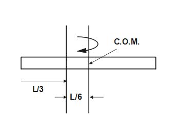
Q5. Moment of inertia of a uniform rod of length L and mass M, about an axis passing through L/3 from one end and perpendicular to its length is

(A) \frac2{27}M\;L^2

(B) \frac1{6}M\;L^2

(C) \frac1{12}M\;L^2

(D) \frac19M\;L^2

Solution

According to Parallel axis theorem ,
I_{parallel\;\;}=\;I_{COM}\;+\;M_{total\;}\;d^2
Here, d= perpendicular distance of parallel axis from the axis passing through C.O.M.
\;I_{COM}\; = Moment of Inertia of rod passing through C.O.M. (perpendicular to rod)
\Rightarrow\;I_{parallel}=\frac1{12}M\;L^2+\;M\;\left(\frac L6\right)^2
\Rightarrow\;I_{parallel}=\;ML^2\;\left[\frac1{12}+\frac1{36}\right]
\Rightarrow\;I_{parallel}=\frac19M\;L^2
(D) is correct option
We have , I_{com}=\frac1{12}ML^2
And \;total\;mass\;of\;rod,\;M_{total}=M
d=\frac L2-\frac L3=\frac L6

Problems 6 of "10 Important Problems for IIT-JEE and NEET"

Q6.F-x equation of a body of mass 4 kg in S.H.M. is F+\;16x\;=0

Here, F is newton and x in meter. The time period of oscillations will be

(A) 6.28\; sec

(B) 3.14\; sec

(C) 1.57\; sec

(D) 1 \; sec

Solution

Given that, F+\;16x\;=0
Also, m= 4kg
F=\;-16x .......(1)
On comparing (1) and (2)
-kx= -16x
\Rightarrow\; k= 16
Time period of S.H.M. is T=2\pi\sqrt{\frac mk}
\Rightarrow T=2\pi\sqrt{\frac4{16}}
\Rightarrow T=2\pi\sqrt{\frac14}
\Rightarrow T=\frac{2\pi}2=\pi
\Rightarrow T=\pi=\;3.14\;sec
(B) is correct option
We already know, the equation of S.H.M. can be written as
F = -kx ......(2)

Problems 7 of "10 Important Problems for IIT-JEE and NEET"

Q7.A ball of mass m moving at a sped v makes a head on collision with an identical ball at rest. If the kinetic energy of the balls after collision is \frac34th of the original. Then the coefficient of restitution is

(A) e=\frac1{\sqrt2}

(B) e=\frac12

(C) e=\frac{\sqrt2}3

(D) e=\frac13

Solution

Given that, mass of each ball = m
According to law of conservation of momentum
m_1 u_1 +m_2 u_2 = m_1 v_1 + m_2 v_2
m v +m *0 = m v_1 + m v_2
m v = m (v_1 + v_2)
v = (v_1 + v_2)
v_1 + v_2 = v.....(1)
Given that , K.E._{net,f\;}=\frac34K.E._{net,i\;}
Therefore, \frac12\;m_1\;v_1^2\;+\;\frac12\;m_2\;v_2^2\;=\;\frac34\left[\frac12\;m_1\;u_1^2\;+\;\frac12\;m_2\;u_2^2\;\right]
\frac12\;m\;\left(\frac{v(1-e)}2\right)^2\;+\;\frac12\;m\;\left(\frac{v(1+e)}2\right)^2\;=\;\frac34\left[\frac12\;m\;v^2\;+\;\frac12\;m\;{\ast\;0}^2\;\right]
\frac12\;\;\frac{v^2\;\left(1+e\right)^2}4\;+\;\frac12\;\;\frac{v^2\;\left(1-e\right)^2}4\;=\;\frac34\left(\frac12\;v^2\;\right)
\Rightarrow\left(1+e\right)^2+\left(1-e\right)^2=3
\Rightarrow1+\;e^2+\;2e\;+\;1\;+\;e^2-2e\;= 3
\Rightarrow\;2\;e^2=\;1
\Rightarrow\;e^2=\;\frac12
\Rightarrow\;e=\;\frac1{\sqrt2}
(A) is correct option
head on collision in mechanics
The formula of coefficient of restitution is :
e=\;\frac{vel. of sepration}{vel. of approach}
e=\;\frac{v_2-v_1}{u_1-u_2}
e=\;\frac{v_2-v_1}{v-0}
v_2- v_1= ev ....(2)
On adding (1) and (2), we get
2 v_2 = v +ev
v_2=\;\frac{v(1+e)}2
On subtracting (2) from (1), we get
2 v_1 = v - ev
v_1=\;\frac{v(1-e)}2

Problems 8 of "10 Important Problems for IIT-JEE and NEET"

Q8.The density of a rod AB increases linearly from A to B. Its mid-point is O and centre of mass is at C. Four axes pass through A, B, O and C , all perpendicular to the length of rod. The moments of inertia of the rod about these axes are I_{A}, I_{B}, I_{O} and I_{C} respectively. Then

(A) I_{A}> I_{B}

(B) I_{C} < I_{B}

(C) I_{O}> I_{C}

(D) All of these

Solution

Problems 9 of "10 Important Problems for IIT-JEE and NEET"

Q9.A simple harmonic oscillation has an amplitude A and time period T. The time required to travel from x=A\;to\;x=\frac A2 is

(A) \frac T4

(B) \frac T5

(C) \frac T6

(D) \frac T{12}

Solution

Problems 10 of "10 Important Problems for IIT-JEE and NEET"

Q10. A geostationary satellite is orbiting the earth at a height of 6R above the surface of earth where R is the radius of earth. The time period of another satellite at a distance of 3.5 R from the centre of earth is

(A) 16.96 hours

(B) 8.48 hours

(C) 9.25 hours

(D) 15.76 hours

Solution

We know that , orbital speed of satellite is
v_o=\;\sqrt{\frac{GM}r}\;
where\;r\;is\;dis\tan ce\;from\;centre\;of\;planet/earth
T\;=\frac{dis\tan ce\;}{speed}=\;\frac{2\pi\;r}{v_o}
T\;=\;\frac{2\pi\;r}{\sqrt{\displaystyle\frac{GM}r}}
T\;=\;2\pi\;\sqrt{\frac{r^3}{GM}}
T\;=\;2\pi\;\sqrt{\frac{r^3}{GM}}\\T^2=\;4\;\pi^2\;\frac{r^3}{GM}
\Rightarrow T^2\;\;\propto\;r^3
This is known as Kepler's Law of period for planetary motion
r= R+ h where R is radius of planet/earth and h is height of satellite from surface of earth
\Rightarrow r_1 = R+ 6R=7R \;and \;r_2= 3.5R
\Rightarrow T\;\propto\;r^\frac32
\frac{T_2}{T_1}=\;\left(\frac{r_2}{r_1}\right)^\frac32
\frac{T_2}{T_1}=\;\left(\frac{3.5R}{7R}\right)^\frac32
\frac{T_2}{T_1}=\;\left(\frac{1}{2}\right)^\frac32
\frac{T_2}{T_1}=\frac1{2\sqrt2}
T_2 =T_1 * \frac1{2\sqrt2}
T_2 =24 * \frac1{2\sqrt2}
T_2 =12* \frac1{\sqrt2}
T_2 =12* 0.707= 8.48 \;hours
(B) is correct option

A capillary tube of radius r is immersed in water and water rises in it to a height h . The mass of water in the capillary tube is 4g . Another capillary tube of radius 2 r is immersed in water. The mass of water that will rise in this tube is:

A capillary tube of radius r is immersed in water and water rises in it to a height h. The mass of water in the capillary tube is 4g. Another capillary tube of radius 2r is immersed in water. The mass of water that will rise in this tube is:

A capillary tube of radius r is immersed in water and water rises in it to a height h. The mass of water in the capillary tube is 4g. Another capillary tube of radius 2r is immersed in water. The mass of water that will rise in this tube is:

(A) 2g

(B) 2.5g

(C) 8g

(D) 16g

Solution

h=\frac{2T\;\cos\theta}{\rho rg}

h=\frac{2T\;\cos\theta}{\left({\displaystyle\frac mV}\right)rg}

h=\frac{2T\;V\:\cos\theta}{mrg}

h=\frac{2T\;\left(\pi\;r^2\;h\right)\;\cos\theta}{mrg}

1 =\frac{2T\;\left(\pi\;r\;\right)\;\cos\theta}{m\;g}

m=\left(\frac{2\pi T\cos\theta}g\right)\;r

m\;\propto\;r

\frac{m_1}{m_2}=\frac{r_1}{r_2}

\frac{4}{m_2}=\frac{r}{2r}

m_2=\;\left(\frac{2r}r\right)\ast\;4

\Rightarrow m_2=\;2\ast\;4=8\;

\Rightarrow m_2=8g\;

(C) option is correct

A capillary tube of radius r is immersed in water and water rises in it to a height h. The mass of water in the capillary tube is 4g. Another capillary tube of radius 2r is immersed in water. The mass of water that will rise in this tube is: