Archives 2025

Pseudo Force

Pseudo Force

Pseudo Force: Understanding the “Fictitious” Force of Non-Inertial Frames

Physics is full of concepts that seem counterintuitive at first but become fascinating once you dive deeper. One such idea is the pseudo force (sometimes called fictitious force).

Whenever you sit in a bus that suddenly accelerates or take a sharp turn in a car, you feel as if some mysterious force is acting on you, pushing you backward or sideways. But in reality, there is no such physical agent pushing you. That’s the world of pseudo force — a force that appears only when we observe motion from a non-inertial reference frame.

This article will explore pseudo force in detail — its definition, origin, mathematical expression, examples, and applications. By the end, you’ll understand why pseudo forces are not “real” in the strict sense, yet are extremely useful in solving problems of mechanics.


1. Reference Frames: The Foundation

Before talking about pseudo force, we need to revisit the concept of reference frames.

  • Reference Frame: A coordinate system from which we observe and measure the motion of objects.

  • Inertial Frame: A frame of reference in which Newton’s laws of motion hold true without modification. Typically, a frame at rest or moving with constant velocity relative to the “fixed stars” is considered inertial.

  • Non-Inertial Frame: A frame that is accelerating or rotating relative to an inertial frame. In such frames, Newton’s laws do not appear to hold unless we introduce additional forces — the pseudo forces.

Example:

  1. Standing on the ground (which we approximate as an inertial frame for most problems), you see a ball falling vertically under gravity.

  2. Sitting in an accelerating car (a non-inertial frame), the same ball seems to move backward, even though no physical backward force is acting on it.


2. What is a Pseudo Force?

Definition:
A pseudo force is an apparent force that arises when we describe motion from a non-inertial frame. It has no physical interaction or agent behind it. Instead, it is introduced mathematically to make Newton’s second law applicable inside a non-inertial frame.

Key Points:

  • It is not a “real” force — it doesn’t arise due to any physical contact or field.

  • It is proportional to the mass of the object.

  • It always acts opposite to the acceleration of the non-inertial frame with respect to the inertial frame.


3. Mathematical Expression of Pseudo Force

Suppose we have:

  • An inertial frame SS.

  • A non-inertial frame S’S’, accelerating with acceleration a⃗0\vec{a}_0 relative to SS.

  • An object of mass mm.

In inertial frame SS:

ma⃗=∑F⃗realm\vec{a} = \sum \vec{F}_{\text{real}}

But in non-inertial frame S’S’:
The acceleration of the object relative to S’S’ is different, so Newton’s law does not balance unless we introduce a fictitious force:

ma⃗′=∑F⃗real+F⃗pseudom\vec{a}’ = \sum \vec{F}_{\text{real}} + \vec{F}_{\text{pseudo}}

Where,

F⃗pseudo=−ma⃗0\vec{F}_{\text{pseudo}} = -m\vec{a}_0

Thus, the pseudo force is directly proportional to the mass of the body and opposite to the acceleration of the non-inertial frame.


4. Everyday Examples of Pseudo Force

(i) The Bus Ride

  • When a bus suddenly accelerates forward, passengers feel a backward push.

  • From the ground (inertial frame), passengers tend to remain at rest due to inertia.

  • From the bus frame (non-inertial), it looks as if a backward force is pushing them. That is the pseudo force.

(ii) Elevator Problems

  • In a downward accelerating lift, a person feels lighter.

  • In an upward accelerating lift, the person feels heavier.

  • The apparent weight is explained by introducing pseudo force equal to −ma0 -ma_0, where a0a_0 is the acceleration of the lift.

(iii) Rotating Reference Frames (Centrifugal Force)

  • When you take a sharp turn in a car, you feel “thrown” outward.

  • From the inertial frame, you are simply trying to maintain a straight-line path, but the car is turning beneath you.

  • From the rotating (car’s) frame, an outward pseudo force called the centrifugal force appears.

(iv) Coriolis Force

  • A special pseudo force observed in rotating frames, responsible for large-scale effects like trade winds, cyclones, and ocean currents on Earth.


5. Pseudo Force vs Real Force

Feature Real Force Pseudo Force
Origin Arises from physical interaction (contact, field, gravity, electromagnetism, etc.) Arises due to acceleration of reference frame
Agent Always has a physical source No physical agent
Newton’s Laws Can be explained directly by Newton’s second law Introduced to make Newton’s laws valid in non-inertial frames
Example Gravitational force, tension, friction Backward push in an accelerating bus, centrifugal force

6. Types of Pseudo Forces (Required for JEE/NEET level)

  1. Linear Acceleration Pseudo Force: Appears when the frame is linearly accelerating.

    • Expression: F⃗pseudo=−ma⃗0\vec{F}_{\text{pseudo}}=-m\vec{a}_0.

  2. Centrifugal Force: Appears in rotating frames, directed radially outward.

    • Expression: Fc=mω2rF_c = m\omega^2 r.


7. Pseudo Force in Elevators – A Classic Example

Let’s derive the apparent weight in a lift:

  • Actual weight = mgmg.

  • Lift acceleration = aa.

In the elevator’s frame:

Apparent weight=N=mg−Fpseudo\text{Apparent weight} = N = mg – F_{\text{pseudo}}

Where pseudo force = −ma -ma.

So,

  • If lift accelerates upward (a>0a>0):
    N=mg+maN = mg + ma. → You feel heavier.

  • If lift accelerates downward (a>0a>0):
    N=mg−maN = mg – ma. → You feel lighter.

  • If a=ga=g (free fall): N=0N=0. → Weightlessness.


8. Pseudo Force in Rotating Frames – Centrifugal and Coriolis

When a body is in a rotating frame (like a rotating merry-go-round), it seems to be “thrown” outward.

  • From inertial frame: The body tries to move tangentially (straight line).

  • From rotating frame: An outward pseudo force F=mω2rF=m\omega^2 r is introduced to explain the tendency.


9. Applications of Pseudo Forces

  1. Engineering and Design:

    • Designing elevators, centrifuges, rotating machines.

    • Vehicle safety, roller-coaster rides, airplane maneuvers.

  2. Meteorology:

    • Coriolis force explains trade winds, cyclones, jet streams.

  3. Space Science:

    • Artificial gravity in rotating space stations uses centrifugal pseudo force.

  4. Daily Life:

    • Balancing in buses or trains, predicting motion while turning.

  5. Education:

    • Helps students reconcile Newton’s laws with real-life observations in accelerating systems.


10. Common Misconceptions

  • Pseudo forces are imaginary, so they are useless.
    Wrong! They are extremely useful tools to simplify analysis in non-inertial frames.

  • Centrifugal force pushes objects outward.
    In reality, no outward force exists in the inertial frame. It is the inertia of motion that makes objects resist circular motion.

  • Pseudo forces are optional.
    If you are working in a non-inertial frame, you must include them to apply Newton’s laws consistently.


11. Visualizing Pseudo Forces

If you are writing this for a blog, here are diagrams you can add (describe in captions):

  1. Passenger being thrown backward in an accelerating bus.

  2. Elevator free-fall with zero apparent weight.

  3. Centrifugal force on a ball tied to a rotating string.

  4. Coriolis effect deflection on Earth.

These visuals help readers connect theory with experience.


12. Pseudo Force and General Relativity – A Deeper Note

Interestingly, pseudo forces give a glimpse into Einstein’s general relativity. Gravity itself can be thought of as a pseudo force that arises because we observe motion from a non-inertial frame of curved spacetime.

In Einstein’s view:

  • Objects in free fall are actually in inertial motion (no real force).

  • Observers standing on Earth feel a downward “gravitational force” only because the Earth is accelerating upward relative to free-falling objects.

Thus, pseudo force in Newtonian mechanics acts as a stepping stone to understanding modern physics.


13. Summary

  • Pseudo force arises in non-inertial frames.

  • Formula: F⃗pseudo=−ma⃗0\vec{F}_{\text{pseudo}} = -m\vec{a}_0.

  • Examples include the backward push in an accelerating bus, elevator apparent weight, centrifugal and Coriolis forces.

  • They are not “real” but are extremely useful in calculations.

  • They connect classical mechanics to deeper ideas in relativity.


14. Conclusion

Next time you feel pushed backward in a speeding bus, remember — it’s not a mysterious hidden hand but your own inertia seen from a non-inertial frame. The pseudo force is a clever tool invented by physicists to keep Newton’s laws working consistently even in accelerating systems.

Understanding pseudo force enriches our grasp of dynamics, helps us appreciate everyday experiences, and lays a foundation for advanced physic

List of Important Physics derivations for Board Examinations (2024-25)

List of Important Physics derivations for Board Examinations (2024-25)

CBSE: Class-XII

Important Physics derivations for Board Examinations

Chapter 7 – Alternating Current (AC)


1.Using phasor diagram, derive an expression for voltage, current and impedance in LCR series circuit connected with alternating source of emf ɛ=sin(ωt + ф) . Also, deduce power factor of circuit  

2.In a series LCR circuit connected to an a.c. source of voltage, ɛ= sinωt.  Use phasor diagram to derive an expression for the current in the circuit. Hence, obtain the expression for the power dissipated in the circuit. Show that power dissipated at resonance is maximum.

3.A series LCR circuit is connected to an ac source. Using the phasor diagram, derive the expression for the impedance of the circuit. Plot a graph to show the variation of current with frequency of the source, explaining the nature of its variation.

4.Derive an expression for average power consumed/dissipated in series LCR circuit connected to alternating source in which the phase difference between volage(emf) and current is ф.

5.Define mean/average value of alternating current and show that the average current for half cycle of A.C. is    , where Io is peak current value.

6.Define mean/average value of alternating current and show that the average current for full cycle of A.C. is  zero  , where Io is peak current value.

7.Define r.m.s. value of alternating current and show that the r.m.s. value of current for half cycle of A.C. is    , where Io is peak current value.

8.Define r.m.s. value of alternating current and show that the r.m.s. value of current for full cycle of A.C. is    , where Io is peak current value.

9.Show that average power dissipated in pure inductor is zero when it is connected to A.C. supply . [2 Marks]

10.Show that average power dissipated in pure capacitor is zero when it is connected to A.C. supply . [2 Marks]

9.Show that average power dissipated in pure inductor is zero when it is connected to A.C. supply . [3 Marks]

10.Show that average power dissipated in pure capacitor is zero when it is connected to A.C. supply . [3 Marks]

11.Show that current leads voltage (emf) by phase angle  in pure capacitive circuit with capacitance C when it is connected to A.C. source. [3 Marks]

12.Show that the voltage (emf) leads current by phase angle  in pure inductive circuit with capacitance C when it is connected to A.C. source. [3 Marks]

Important Physics derivations for Board Examinations

Chapter 6 – Electromagnetic Induction (EMI)6

1.A conducting rod of length ℓ is kept perpendicular to uniform magnetic field \overrightarrow B. It is moved along the magnetic field with a velocity  \overrightarrow v. Derive the expression of e.m.f. (motional e.m.f.) induced in the conductor.

Important Physics derivations for Board Examinations

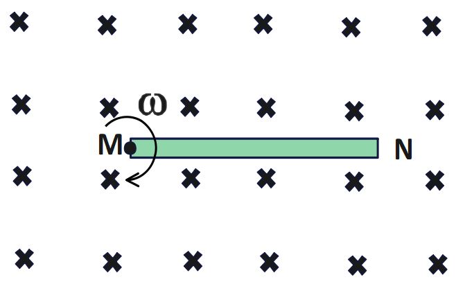
2.A metallic rod MN of length ℓ is rotated with angular velocity \omega about an axis passing through one of its end and perpendicular to the plane of the paper, in uniform magnetic field \overrightarrow B as shown in figure. Derive an expression for the induced emf (motional e.m.f.) developed between the end points M and N.

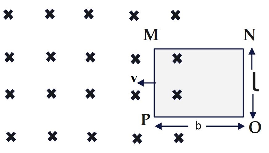
3. The figure shows a rectangular conducting frame MNOP of resistance R placed partly in a perpendicular magnetic field \overrightarrow B and moved with velocity \overrightarrow v as shown in the figure. 

Important Physics derivations for Board Examinations

Obtain the expressions for the

(a) induced current in the loop

(b) force acting on the arm ‘ON’ and its direction, and

(c) power required to move the frame to get a steady emf induced between the arms MN and PO.

4.Two concentic circular coils X and Y of radii r_1 and r_2 (r_1>>r_2) having N_1 and N_2 turns respectively are placed coaxially with centres coinciding. Obtain an expression for
(i) the mutual inductance for the arrangement, and
(ii) the magnetic flux linked with coil Y when current I flows through coil X.

5.Obtain the expression for the mutual inductance of two long co-axial solenoids S_1 and S_2 wound one over the other , each of length L and radii r_1 and r_2 and n_1 and n_2 number of turns per unit length , when a current I is set up in the outer solenoid S_2

6. Define self-inductance of a coil. Derive the expression for magnetic energy stored in an inductor L connected across a source of emf to build up a current I through it.

7.Define self-inductance of a coil. Derive the expression for self-inductance of a solenoid of length L and  and r, having N turns. 

8. A rectangular coil of area A, having number of turns N is rotated at ‘f ‘ revolutions per second in a uniform magnetic field B, the field being perpendicular to the coil. Prove that the maximum emf induced in the coil is 2\pi fBAN

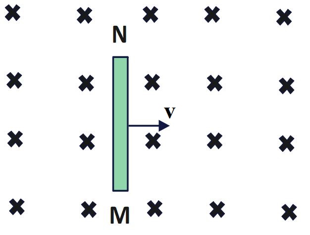
9.A metallic rod MN of length ℓ moves with linear velocity \overrightarrow v , perpendicular to uniform magnetic field \overrightarrow B as shown in figure. Derive an expression for the induced emf (motional e.m.f.) developed between the end points M and N.
Important Physics derivations for Board Examinations

Important Physics derivations for Board Examinations

Chapter 5 – Magnetism and Magnetic Materials

1.Derive relationship (\mu_{r\;}=\;1+\;\chi_m) between magnetic susceptibility \chi_m and relative permeability \mu_r.

2. Show that a current carrying solenoid is as equivalent to a tiny bar magnet.

Important Physics derivations for Board Examinations

Chapter 4 – Moving Charges and Magnetism

1. Using Biot-Savarat law, derive an expression for the magnitude of the magnetic field at a distance radius ‘r’ from a finite straight wire carrying current ‘I’. Also, deduce the magnetic field due infinitely long straight wire. 

2.(i) State Biot – Savart law in vector form expressing the magnetic field\overrightarrow B due to an element \overrightarrow {dl} carrying current I at a distance \overrightarrow r from the element.

(ii) Derive an expression for the magnitude of the magnetic field at the centre of a circular loop of radius r carrying a steady current I. Draw the field lines due to the current loop.

3. Use Biot-Savart law to derive the expression for magnetic field B at a point P on the axis (distance x from centre) of a circular coil of radius ‘r’ carrying current ‘I’ and hence find the magnetic field at the centre ‘O’ of the circular coil carrying current.

4. Using Ampere’s circuital law, obtain an expression for the magnetic field due a infinitely long straight wire carrying current ‘I’.

5.Using Ampere’s circuital law, obtain an expression for the magnetic field along the axis of a current carrying solenoid of length l and having N number of turns.

6.Derive the expression for force per unit length between two long straight parallel current carrying conductors. Hence define one ampere.

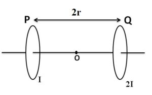
7.Two identical circular loops, P and Q, each of radius r and carrying current I and 2I respectively are lying in parallel planes such that they have a common axis. The direction of current in both the loops is clockwise as seen from O which is equidistant from both the loops. Obtain the expression for the magnitude of the net magnetic field at point O.

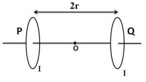
8.Two identical circular loops, P and Q, each of radius r and carrying equal currents are kept in the parallel planes having a common axis passing through O. The direction of current in P is clockwise and in Q is anti-clockwise as seen from O which is equidistant from the loops P and Q. Obtain the expression for the magnitude of the net magnetic field at O.

9. A rectangular coil PQRS of sides ‘l’ and ‘b’ carrying a current I is subjected to a uniform magnetic field \overrightarrow B  acting perpendicular to its plane. Obtain the expression for the torque acting on it.

10.Deduce the expression for the magnetic dipole moment of an electron orbiting around the central nucleus.

11.Describe the working principle of a moving coil galvanometer. Why is it necessary to use
(i) a radial magnetic field and
(ii) a cylindrical soft iron core in a galvanometer? Write the expression for current sensitivity of the galvanometer.
Can a galvanometer as such be used for measuring the current?

12.(a) Discuss the conversion of galvanometer  to  ammeter which can measure current ranging from 0 to I. Deduce the expression for ammeter current I if galvanometer can allow maximum current  I_g to pass through itself.

(b) Explain, giving reasons, the basic difference in converting a galvanometer into
(i) a voltmeter and
(ii) an ammeter.

13.(a) Discuss the conversion of galvanometer  to  voltmeter which can measure voltage ranging from 0 to V. Deduce the expression for  potential difference V that it can measure  if galvanometer can allow maximum current  I_g to pass through itself.

(b) Explain, giving reasons, the basic difference in converting a galvanometer into
(i) a voltmeter and
(ii) an ammeter.

14.(a) Use Biot-Savart law to derive the expression for the magnetic field due to a circular coil of radius R having N turns at a point on the axis at a distance ‘x’ from its centre. Draw the magnetic field lines due to this coil.
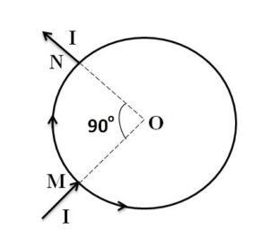
(b) A current ‘I’ enters a uniform circular loop of radius ‘R’ at point M and flows out at N as shown in the figure.

Obtain the net magnetic field at the centre of the loop.

Important Physics derivations for Board Examinations

Chapter 3 – Current Electricity

1.Derive an expression for drift velocity of free electrons in a conductor in terms of relaxation time.

2.Explain the term ‘drift velocity’ of electrons in a conductor. Hence obtain the expression for the current through a conductor in terms of ‘drift velocity’

3.Derive an expression for the resistivity of a good conductor, in terms of the relaxation time of electrons.

4.(i) Define the term drift velocity.
(ii) On the basis of electron drift, derive an expression for resistivity of a conductor in terms of number density of free electrons and relaxation time. On what factors does resistivity of a conductor depend? 
             (OR)
Derive an expression for the resistivity \rho=\frac m{ne^2\tau} a good conductor, in terms of the relaxation time of electrons.

5.Use Kirchhoff’s rules to derive conditions for the balanced Wheatstone bridge.

6.Using the concept of drift velocity of charge carriers in a conductor, deduce the relationship between current density and resistivity/conductivity of the conductor. 

7.Derive an expression for the current density of a conductor in terms of the drift speed of electrons. 

8.A number of identical cells n, each of emf e, internal resistance r connected in series are charged by a d.c. source of emf elr using a resistor R.
(i) Draw the circuit arrangement.
(ii) Deduce the expressions for
(a) the charging current and (b) the potential difference across the combination of the cells.

9.Find the relation between drift velocity and relaxation time of charge carriers in a conductor. A conductor of length L is connected to a d,c. source of emf ‘E’. If the length of the conductor is tripled by stretching it, keeping ‘E’ constant, explain how its drift velocity would be affected.

Important Physics derivations for Board Examinations

Chapter 2 – Electrostatic Potential and Capacitance

1.Derive an expression for capacitance of isolated spherical conductor.

2. Derive the expression for the capacitance of a parallel plate capacitor having plate area A and plate separation d.

3.Derive an expression for capacitance of parallel plate capacitor completely filled with dielectric of dielectric constant K.

4.Derive an expression for capacitance of parallel plate capacitor partially filled with dielectric of width t (t < d).

5.Explain using suitable diagrams, the difference in the behavior of a (a) conductor and (b) Dielectric in the presence of external electric field. Define the polarization of dielectric and write its relation with susceptibility. Also derive relationship between susceptibility and dielectric constant.

6. Derive an expression for potential at any point P on axial line of dipole of length ‘2a’ at a distance ‘r’ from the center of dipole. Also deduce the potential for short dipole. 

7. Derive an relationship between electric field and potential gradient, E = – dV/dr

8.Show that the potential at any point on equatorial line of a dipole at a distance ‘r’ from the center of dipole is zero. 

Important Physics derivations for Board Examinations

Chapter 1 – Electric Charges and Fields

1.Derive an expression for electric field intensity at any point P on axial line of dipole of length ‘2a’ at a distance ‘r’ from the center of dipole. Also deduce the electric field intensity for short dipole. 

2.Derive an expression for electric field intensity at any point P on equatorial line of dipole of length ‘2a’ at a distance ‘r’ from the center of dipole. Also deduce the electric field intensity for short dipole. 

3.Derive an expression for electric field intensity due to short dipole at any general point at a distance ‘r’ from the dipole of dipole moment \overrightarrow p .

4. Derive an expression for torque acting on electric dipole  placed in uniform electric field \overrightarrow E . Also , explain the stable and unstable equilibrium of dipole position on the basis of torque experienced by it. 

5.Derive an expression for electrostatic potential energy of  electric dipole  placed in uniform electric field \overrightarrow E . Also , explain the stable and unstable equilibrium of dipole position on the basis of P.E. of dipole.

6. Using Gauss’ Law , derive an expression for electric field intensity due to uniformly charged infinitely long straight wire having linear charge density ‘\lambda‘ at a distance r from it.

7.Using Gauss’ Law , derive an expression for electric field intensity due to uniformly charged infinite thin sheet having surface charge density ‘\rho

8.Derive an expression for the electric field due to a uniformly charged thin spherical shell (i) outside the shell and (ii) inside the shell using Gauss’s law. Also draw required graph showing variation of electric field with distance from the center of spherical shell.

Now, we have gone through frequently asked "Important Physics derivations" in CBSE Board Examinations. Click here to know more essential topics related to Electromagnetism.